


Difficulté
Modérée
Étapes
7
Temps nécessaire
02:00:00 - 03:00:00

Ce tutoriel a été créé par la communauté
User contributed
Introduction
Remplacer les 3 supports moteur sur une Renault Mégane 2 1.5dci 82cv de 2003
Parts
-
-
Mise en sécurité du véhicule : démontage et remontage de la roue
-
-
Retirer la plaque de protection sous moteur fixée par 7 boulons de 13.
-
-
-
Positionner un cric sous le véhicule entre le moteur et la boite à vitesse. En intercalant une cale en bois, soulager légèrement l'ensemble du moteur.
-
Déclipser les 3 connecteurs reliés au calculateur en faisant pivoter les leviers des connecteurs en "dessinant" un demi cercle après avoir appuyé sur l'ergot de verrouillage à l'aide d'un tournevis. Ne pas forcer
-
Retirer les boulons de 13 du bac de la batterie ainsi que celui de la bride de fixation.
-
Déssérer le collier de la durite d'air sortie boîte à air, incliner le bac de la batterie à 90° vers la gauche afin d'éviter de déclipser les fixations des faisceaux électriques (fragile, en cas de casse mettre des rislans au remontage). Déposer le calculateur qui est juste emboîté sous le bac.
-
-
-
Déboîter les durites d'air en commençant par celle côté radiateur, ensuite côté pare-brise puis celui de l'entrée de la boîte à air. Déposer la boîte à air en la tirant vers soi, elle est juste clipsée en bas à gauche et sur le côté droit. Tout est très millimètré et il faut jouer sur l'inclinaison des durites.
-
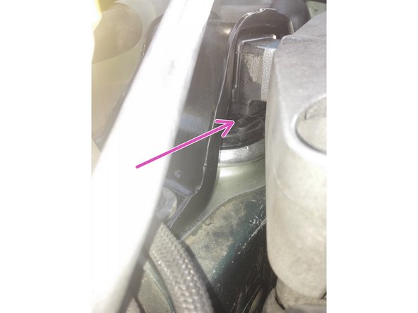
Nous arrivons à cette configuration où nous pouvons apercevoir le support moteur.
-
Déssérer l'écrou central du support qui maintient le moteur à l'aide d'une douille de 16 et un cliquet. Veillez à avoir soulagé le moteur à bonne hauteur, si pas assez soulagé, le moteur descendra de trop, si trop soulagé, il ne descendra pas et gênera au moment d'ôter le support moteur.
-
Écrou au dessus, boulon en dessous, dévisser les écrous du support au chassis à l'aide d'une douille de 18. Maintenir les boulons par le dessous afin d'éviter de les faire tomber.
-
Retirer le support moteur en le tirant vers le haut, si blocage faire levier avec un ou deux tournevis plat. Penser à descendre suffisamment le moteur pour dégager la vis centrale.
-
-
-
Centrer au mieux le nouveau support avec la vis centrale et les trous de fixation au chassis. Idéalement se faire aider par un tiers qui pourra ajuster le cric ou déplacer le moteur de quelques millimètres à la main ou à l'aide d'un levier afin de bien centrer le tout.
-
Serrer au couple de 62 Nm les deux boulons extérieurs, puis l'écrou central également à 62Nm. Descendre le cric, s'assurer du bon remontage, puis tout remonter en procédant dans l'ordre inverse du démontage.
-
Nous pouvons comparer les deux supports, ici vu de dessous, une partie du caoutchouc est désolidarisée du reste.
-
-
-
Aussi appelé tampon hydro-élastique, il se trouve à gauche de la distribution face au capot.
-
On positionne cette fois le cric sous le carter d'huile, juste à gauche du bouchon de vidange et toujours avec une bonne cale en bois. On soulage le moteur sans excès.
-
Desserrer le boulon transversal de 16 qui relie le support au moteur, le déplacer vers la gauche contre le bocal de liquide de refroidissement, nous ne pouvons pas l'extraire pour le moment. Ajuster la hauteur du moteur avec le cric de façon à ce que le boulon soit le plus possible à l'horizontale.
-
Étant difficile d'accès et bien serré voici une petite astuce avec deux clés plates. Ne pas utiliser de clé à fourche sur le boulon au risque de l'arrondir. Il est possible de déclipser la poire à gazole ainsi que les durites pour gagner de la place, mais ne pas forcer sur les conduites de climatisation en aluminium.
-
Retirer les 4 boulons de la coiffe du support moteur à l'aide d'une douille de 16.
-
Terminer avec les 3 boulons du support toujours avec une douille de 16. Extraire la coiffe et le support en pivotant entre la conduite supérieure de climatisation et le carter de distribution.
-
-
-
Procéder en sens inverse pour le remontage, bloquer en priorité le nouveau support en serrant les 3 boulons au couple de 62Nm, ensuite les 4 boulons de la coiffe toujours au même couple et pour finir le boulon transversal à 105Nm. Ne pas oublier de reclipser la poire et les durites si besoin.
-
Nous observons ici la différence d'affaissement entre le nouveau et l'ancien support.
-
Sur le support neuf et malgré le poids du moteur, nous avons toujours un espace entre les deux parties en caoutchouc. Il est possible de contrôler l'affaissement d'un ancien support en insérant une cale de 0.5mm à cet endroit, si elle ne rentre pas ou ne coulisse pas librement, le support est défectueux.
-
-
-
Pour terminer, retirer les deux boulons de 18 du support inférieur. Il est relié à droite sur la photo au chassis du véhicule, et à gauche au "tirant" fixé lui même à la boîte à vitesse. Inutile de déposer le tirant, les deux boulons retirés, pivoter le support de gauche à droite pour l'extraire.
-
Ici plus besoin de soulager le moteur, il aura juste un effet balancier ajustable à la main pour faciliter les opérations.
-
support inférieur
-
tirant
-
Reposer le nouveau support avec ses deux boulons au couple de 105Nm. Si vous avez été obligé de déposer le tirant, le boulon de gauche sur la photo se resserre à 62Nm.
-
Nous observons ici la nécessité de remplacer ce support.
-


Les supports moteurs fatigués engendrent des vibrations dans l'habitacle, notamment au ralenti. Les supports craquelés/fissurés doivent faire l'objet d'une surveillance particulière mais ne sont pas forcément défectueux. Un support hydro-élastique fuyant doit être remplacé comme tout support déchiré/cassé. D'une manière générale, le support droit côté distribution provoque le plus de vibrations, il peut-être accompagné selon les motorisations (pas sur la mienne) de ce support à remplacer également Changement support moteur supérieur droit sur Renault Megane 2.
Vient ensuite le support inférieur provoquant principalement des à-coups aux passages de vitesses. Celui sous la batterie reçoit peu de contraintes mécaniques et donc subit moins d'usure. Pour terminer, les vibrations ressenties n'ont pas toujours seulement pour cause un support défectueux, mais ils peuvent être la conséquence d'une anomalie moteur comme l'injection ou allumage qui provoquent du mouvement et des vibrations => usure prématurée des supports.
Annulation : je n'ai pas terminé ce tutoriel.
16 autres ont terminé cette réparation.
18 commentaires
Merci beaucoup pour ce tuto très explicite documenté précis et courtois !!
Cordialement, Bernard
marretbernard - Résolu à la publication Réponse
bonsoir j ai aussi des tremblement au ralenti sur ma sceni2 phase 2 130 1.9 dci 2007j ai aussi du mal a demarer a froid est ce du aussi au support moteur qui Son fatiguer sinon elle demarre bien a chaud est ce que sa peut prevenir de ca car j ai fait toute la revision en vous remerciant d avance en attendant vos response merci joakdecastro@gmail.com
Joaquim De Castro - Résolu à la publication Réponse
Super, merci,
Pas contre pour celui sous la batterie, vrai galère, la boite à air est très dur à enlever, il faut enlever le manchon derrière calandre avant, avec peu de mou, sinon impossible. En plus il bouge pas, il faut d’abord devisser jusque en haut le boulon centrale, et taper avec le boulon + cale pour le décoller du support, cric legerement plus bas que la boite (2cm) Et attention aux deux autres boulons, ils sont pas fixes et tombe si vous devisser à fond.
Chez moi le boulon transversal était cassé en deux, tu m’étonne que ca vibrait. Parait que c’est fréquent, prévoyer le. 12x110mm.
sarl davali - Résolu à la publication Réponse
bonjour,
J’ai du mal a sortir le support gauche coté boite, il reste coincé …. avec un bras de levier tournevis j’arrive a le faire bouger mais sans le sortir.
De combien suis-je autorisé a “descendre” le moteur pour soulager le support et faciliter sa sortie ? 1cm ? 5cm ?
Merci :-)
Olivier
olivier de smet - Résolu à la publication Réponse