


Difficulté
Modérée
Étapes
17
Temps nécessaire

En cours
Ce tutoriel est en cours de création. Revenez de temps en temps pour voir les modifications.

Ce tutoriel a été créé par la communauté
User contributed
Introduction
Intervention effectuée sur une Renault Twingo 2 phase 2, moteur 1.5 dCi 75ch.
C'est une voiture que j'ai acheté d'occasion, je n'ai ni manuel d'utilisation ni revue technique par conséquent je ne connais ni les contenances ni les couples de serrage.
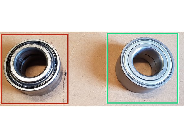
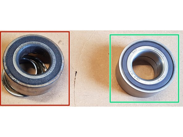
Le roulement neuf a un sens de montage, le côté magnétique du roulement doit étre en contact avec le capteur ABS.
Le roulement neuf est un SKF VKBA 3637.
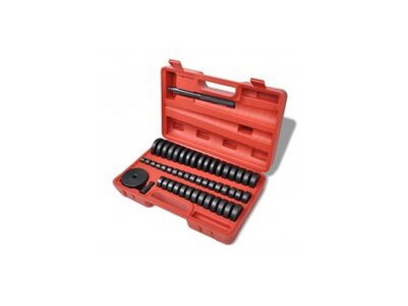
Pour cette intervention, j'ai eu besoin d'outils spécifiques tels qu'une presse, un jeu de disque d'extraction et un décolleur de roulement.
-
-
Dans un premier temps retirez l'écrou de cardan à l'aide d'une douille de 30mm.
-
Retirez la roue : Mise en sécurité du vehicule
-
-
-
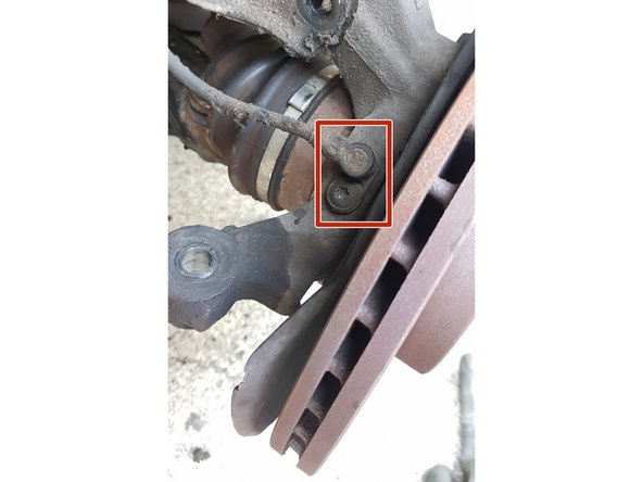
Avec une clé mixte de 16mm et un embout torx T30, retirez l'écrou puis désaccouplez la biellette.
-
-
-
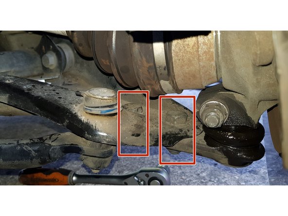
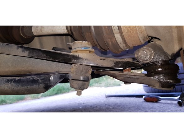
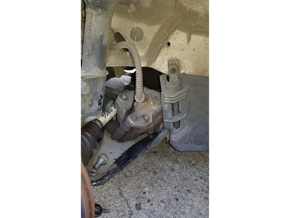
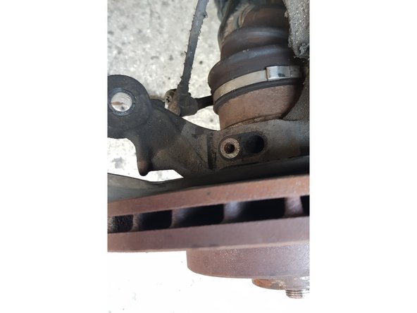
Avec une douille et une clé mixte de 18mm, retirez les 2 écrous ainsi que la vis côté intérieur puis désaccouplez la rotule du triangle.
-
-
-
Si vous avez du mal à désaccoupler la rotule, vous pouvez utiliser un pied de biche ou une barre à mine pour faire levier sur le triangle en prenant appui sur la barre stabilisatrice.
-
-
-
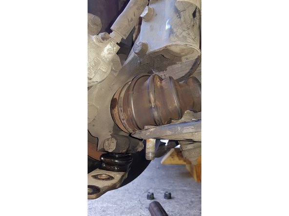
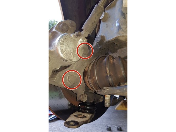
Avec une douille de 18mm, retirez les 2 vis.
-
Déposez l'étrier sur le triangle.
-
L'étrier ne doit surtout pas reposer sur son flexible!
-
-
-
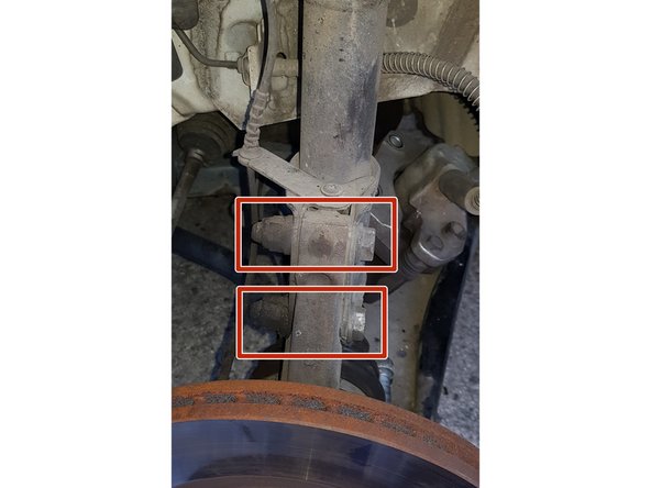
Avec une douille et une clé mixte de 18mm, retirez les 2 boulons.
-
Vous pouvez utiliser un chasse-goupilles pour retirer les vis.
-
-
-
Avec un embout torx T40, retirez les 2 vis puis le disque.
-
-
-
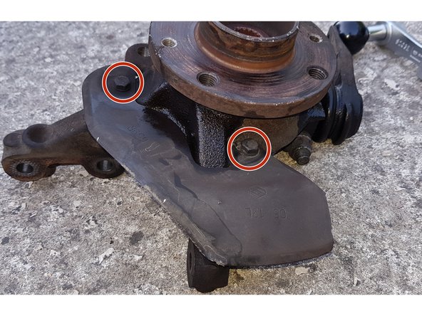
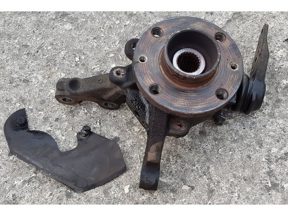
Avec une clé de 10mm, retirez les 2 vis puis la tôle.
-
-
-
J'ai utilisé un jeu de disque pour l'extraction de roulements.
-
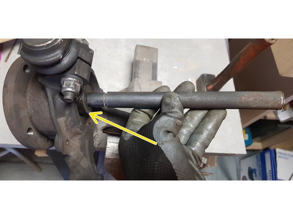
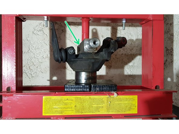
Placez la fusée dans un étau.
-
Placez un disque de Ø37mm à l'arrière de la fusée.
-
Tapez sur le disque à l'aide d'un tube et d'un marteau pour extraire le moyeu.
-
-
-
-
J'ai utiliser un décolleur de roulement pour essayer de sortir la bague intérieure.
-
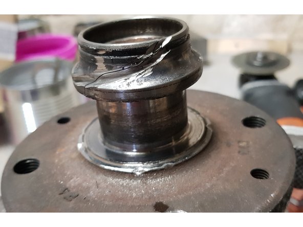
Résultat médiocre sur le moyeu.
-
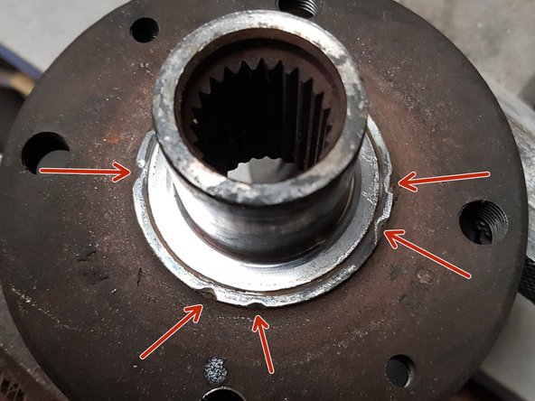
Du coup, je n'ai pas insisté et ai utilisé la disqueuse.
-
Attention, il ne faut surtout pas endommager l'arbre.
-
-
-
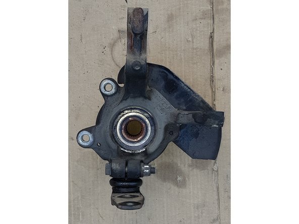
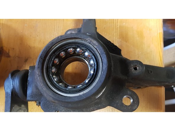
Ancienne pièce
-
-
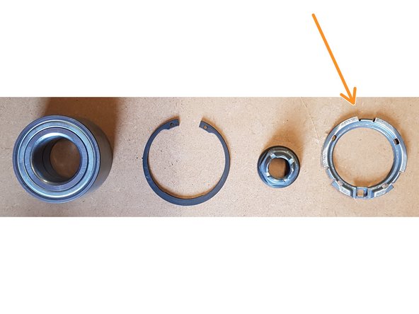
Avec le roulement neuf sont fournis un circlip, un écrou et une bague de fixation du capteur ABS. Je n'ai pas utilisé cette dernière.
-
-
-
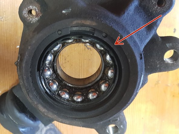
Ce roulement est équipé d'une bague d'impulsion magnétique. Il est impératif que la bague d'impulsion soit en face du capteur ABS lors du montage du roulement.
-
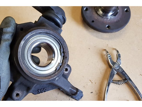
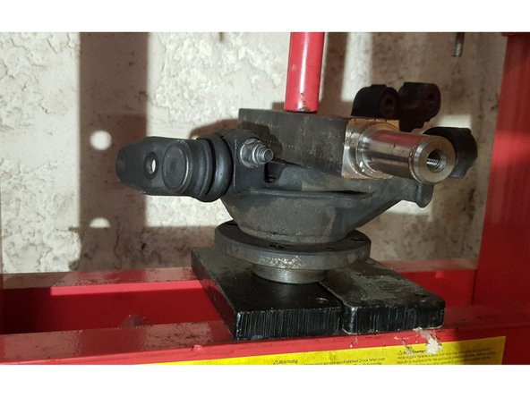
Insérez le roulement neuf dans la fusée.
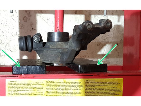
-
Pour ce faire, j'ai placé le roulement sur les cales, puis la fusée puis une pièce carrée en acier sur laquelle je prends appui pour presser.
-
Une fois que la fusée est en contact avec les cales, je libère la pression, place un disque - dont le diamètre est 1mm plus petit que le diamètre du roulement - entre les cales et le roulement, puis je presse à nouveau pour que le roulement arrive en butée.
-
Pour finir, placez le circlip neuf.
-
-
-
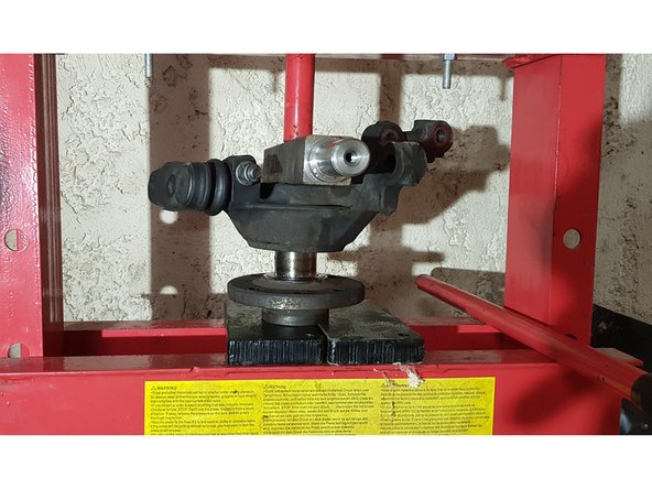
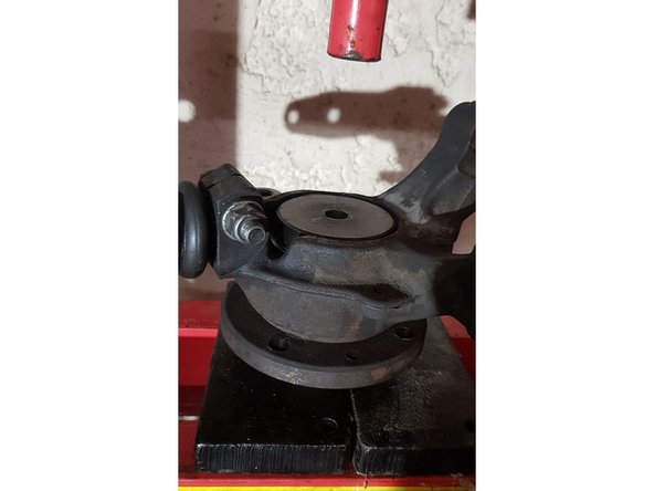
Il faut avant tout placer un disque de Ø65mm côté intérieur de la fusée pour éviter que le moyeu chasse la bague intérieure du roulement.
-
Placez le moyeu sous la fusée puis pressez.
-
Le reste du remontage s'effectue en sens inverse.
-


Annulation : je n'ai pas terminé ce tutoriel.
Une autre personne a terminé cette réparation.