


Difficulté
Difficile
Étapes
30
Temps nécessaire
02:00:00

Ce tutoriel a été créé par la communauté
User contributed
Introduction
Opération effectuée sur VW Polo III Restylée 1.4 i 60cv.
Outils
-
-
Avant toute chose placez le moyeu neuf dans votre congélateur.
-
Dévissez l'écrou de cardan avec une douille de 32 pans.
-
Une douille de 12 pans est impérative!
-
Mise en sécurité du véhicule : démontage et remontage de la roue
-
-
-
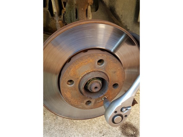
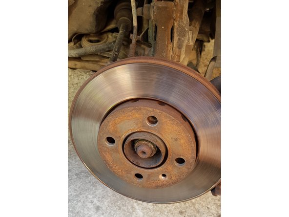
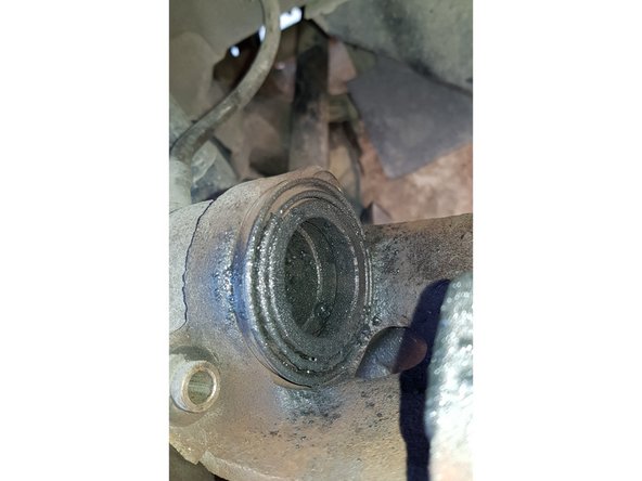
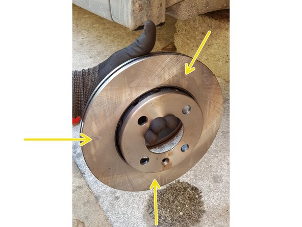
Disque de frein
-
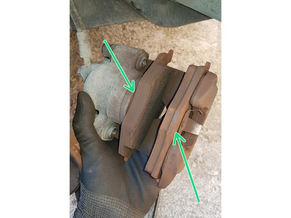
Plaquette côté piston
-
Insérez un tournevis plat entre le disque et la plaquette côté piston et faîtes levier pour repousser le piston.
-
Une fois le piston repoussé vérifiez le niveau du liquide de frein qui doit être entre ...
-
… le mini ….
-
…. et le maxi.
-
Si le niveau dépasse le maxi retirez-en avec une seringue.
-
-
-
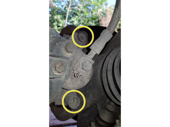
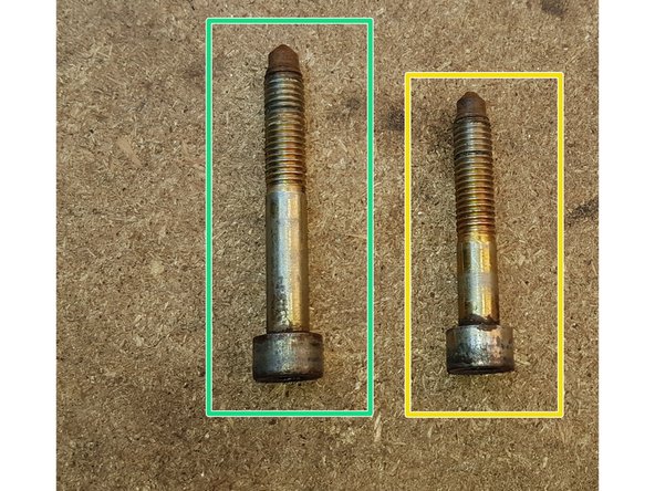
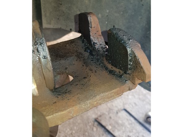
Les 2 vis qui maintiennent l'étrier ne font pas la même longueur donc pensez à repérer leur position.
-
Vis du haut
-
Vis du bas
-
-
-
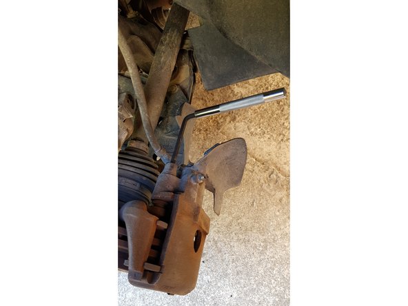
Tirez la partie supérieure de l'étrier vers l'extérieur puis vers le haut.
-
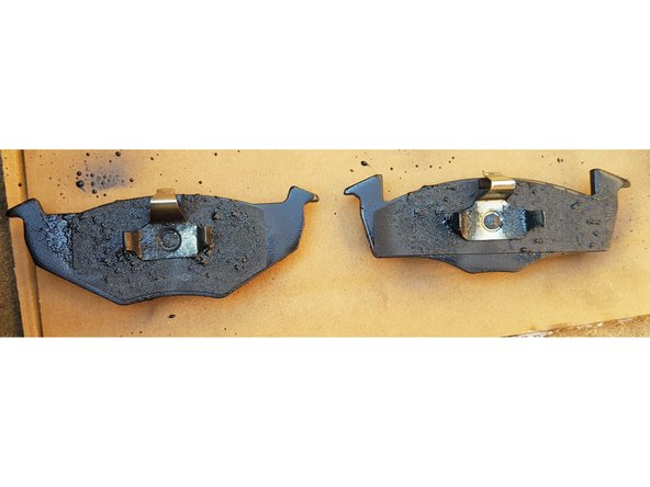
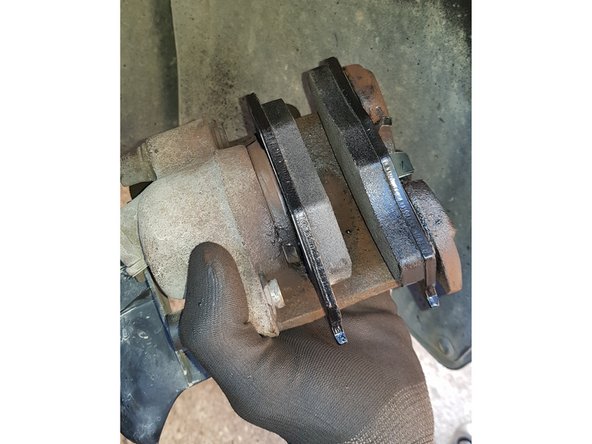
Les faces inférieures des plaquettes sont différentes donc pensez à repérer l'emplacement de chaque plaquette avant démontage puis sortez-les.
-
-
-
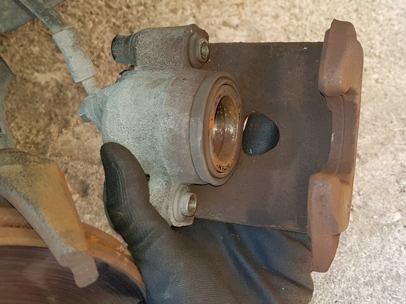
Avec un serre-joint et une cale en bois que vous positionnerez sur le piston repoussez celui-ci à fond.
-
Il est possible de repousser le piston entièrement dès l'étape 2 avec le tournevis.
-
Le piston n'est pas vissé donc vous n'aurez pas besoin d'un repousse-piston, un serre-joint fera l'affaire.
-
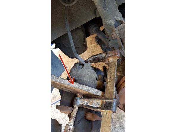
Posez l'étrier sur l'amortisseur.
-
Veillez à ce que le flexible de frein ne soit pas tendu.
-
-
-
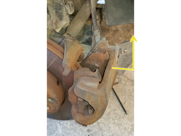
Le disque est maintenu par une vis qu'il est possible de retirer grâce à un tournevis Phillips PH3.
-
Retirez le disque.
-
-
-
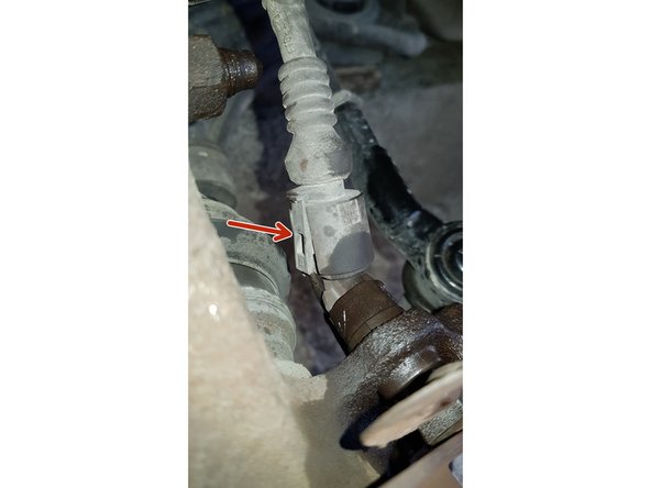
Débranchez la connectique
-
Avec une clé BTR 5mm dévissez la vis puis retirez le capteur.
-
-
-
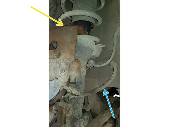
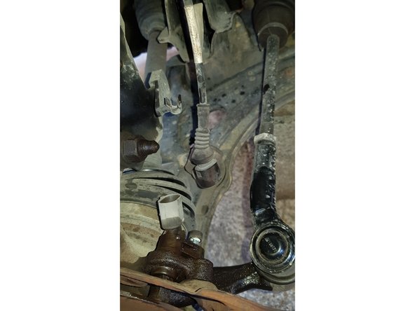
Avec une clé de 18mm débloquez les écrous de la jambe d'amortisseur.
-
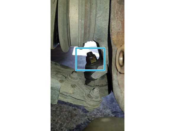
Avec une clé de 16mm débloquez l'écrou de la rotule de suspension
-
-
-
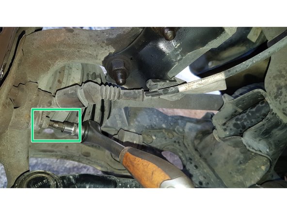
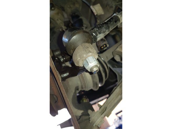
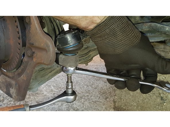
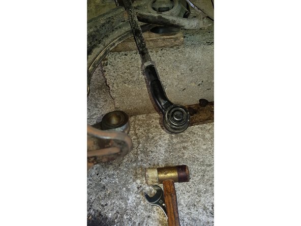
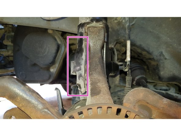
Avec une clé BTR de 6mm et une clé plate de 16mm retirez la biellette de direction de la fusée.
-
-
-
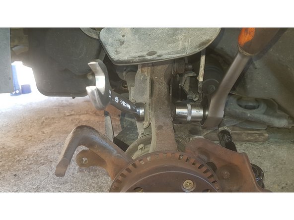
Retirez les 2 boulons de l'amortisseur.
-
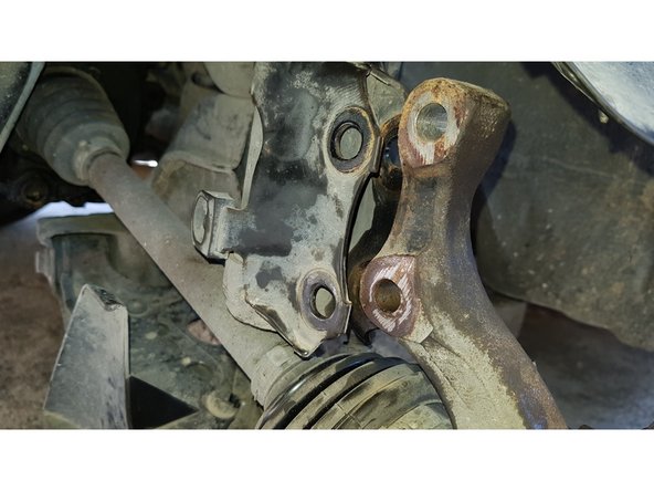
Avec une clé de 16mm retirez l'écrou de la rotule de suspension.
-
Désaccouplez la fusée de la jambe d'amortisseur.
-
-
-
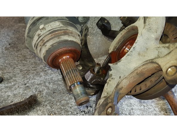
Sortez le cardan du moyeu puis sortez le moyeu de la rotule de suspension.
-
-
-
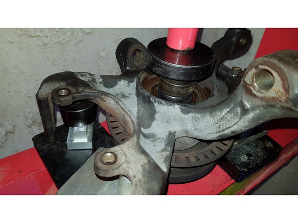
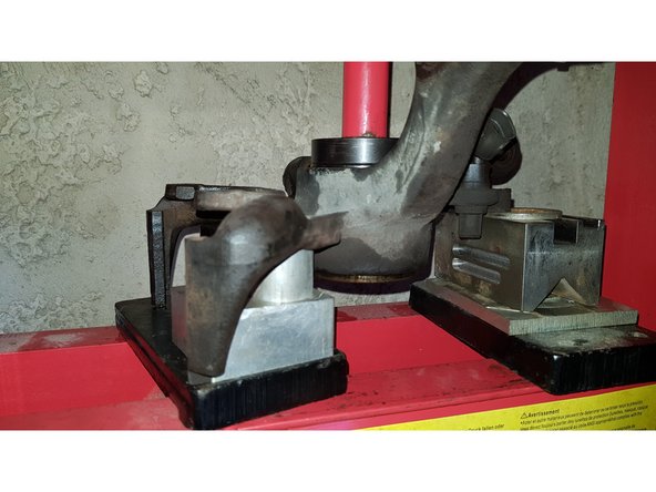
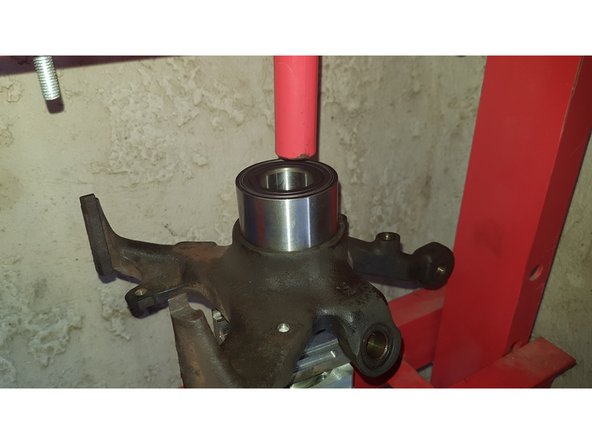
Avec une clé de 10mm retirez les 3 vis.
-
-
-
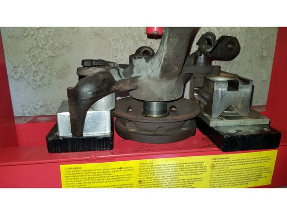
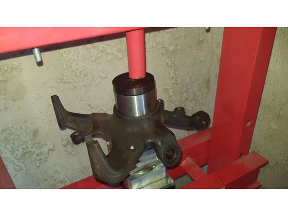
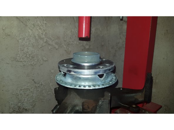
Assurez-vous que l'ensemble soit bien dans l'axe de l'arbre de la presse pour que le moyeu sorte bien droit.
-
Faites en sorte que les cales porte sur l'arbre du moyeu et non pas sur le roulement.
-
-
-
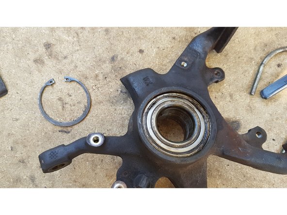
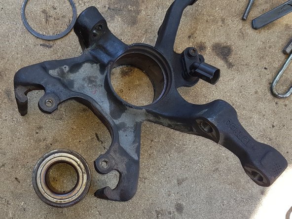
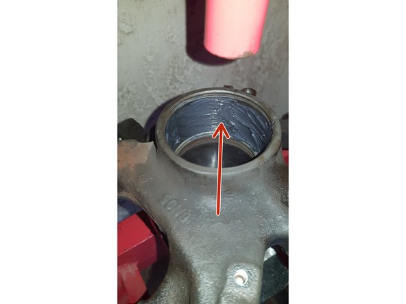
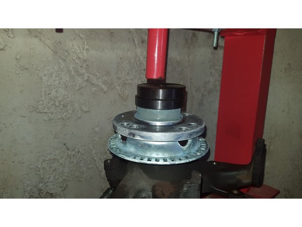
Retirez le circlip pour pouvoir procéder à l'extraction du roulement.
-
-
-
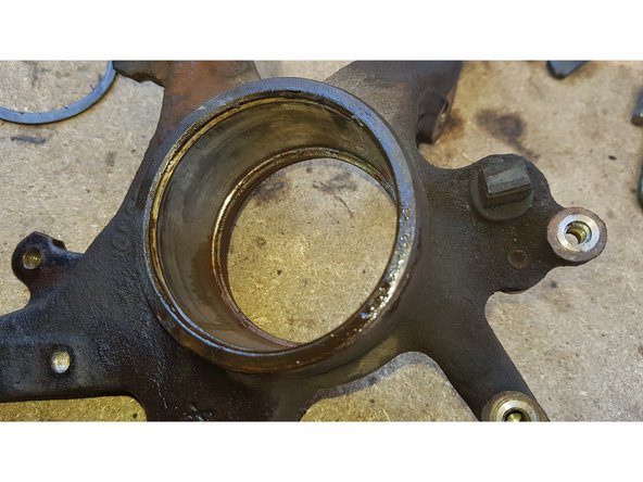
Avec du papier absorbant nettoyez la portée du roulement.
-
-
-
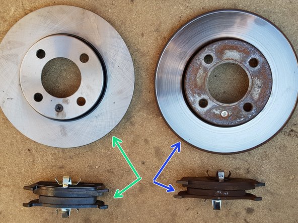
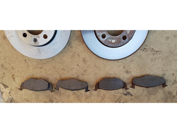
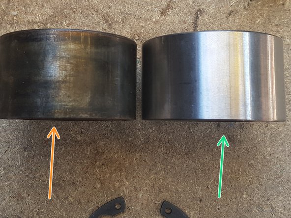
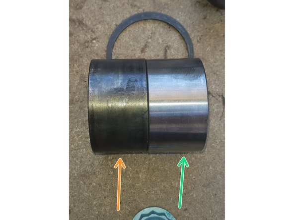
Anciennes pièces
-
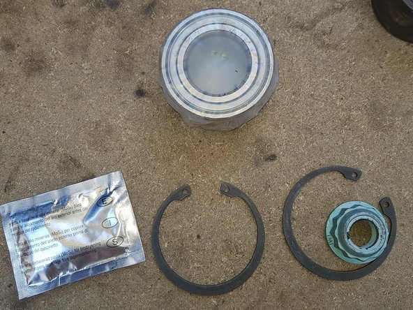
Pièces neuves
-
Avec le roulement neuf sont livrés la graisse, l'écrou de cardan et 2 circlips.
-
Vous n'aurez besoin que d'un circlip.
-
-
-
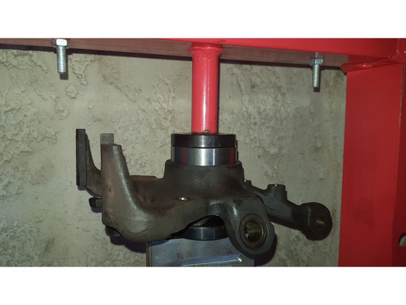
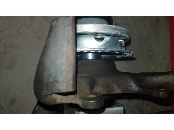
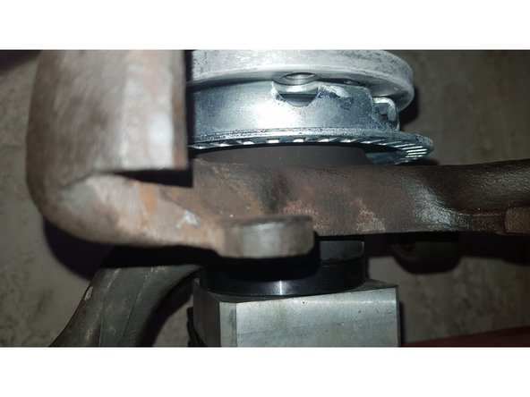
Positionnez la fusée dans le sens inverse que celui dans lequel elle était lors de l'extraction du roulement.
-
Enduisez la portée du roulement de graisse.
-
Présentez le roulement neuf.
-
Placez une cale au-dessus.
-
Veillez à ce que le roulement soit bien positionné pour qu'il puisse rentrer bien droit dans la fusée puis avec la presse enfoncez-le dans son logement.
-
-
-
Placez le circlip dans son emplacement pour bloquer le roulement dans la fusée.
-
Côté extérieur
-
Côté intérieur
-
-
-
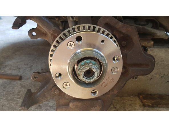
Sortez votre moyeu du congélateur puis présentez-le sur la fusée.
-
Placez une cale au-dessus.
-
Veillez à ce que le moyeu soit bien positionné pour qu'il puisse rentrer bien droit dans le roulement puis avec la presse enfoncez-le dans son logement.
-
-
-
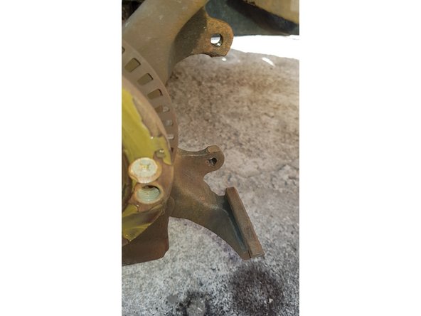
Replacez la plaque de protection du disque sur la fusée puis l'ensemble sur le véhicule en remontant les 2 boulons de la jambe d'amortisseur, l'écrou de la rotule de suspension, l'écrou de cardan et la biellette de direction.
-
Enduisez la portée du moyeu de graisse cuivrée.
-
-
-
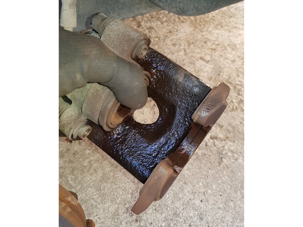
Avec une brosse métallique nettoyez les guides de plaquettes
-
Puis pulvérisez de l'anti-bruits afin d'éviter les sifflements au freinage.
-
-
-
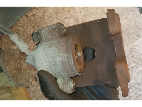
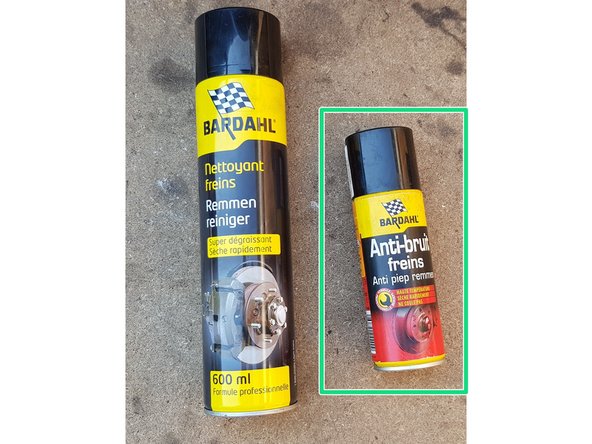
Pulvérisez du nettoyant-frein sur l'étrier pour retirer le plus gros de la poussière.
-
Puis nettoyez-le avec une brosse métallique.
-
-
-
Pulvérisez de l'anti-bruits sur toutes les surface de contact.
-
Ne pas en pulvériser sur les surfaces de frottement.
-
-
-
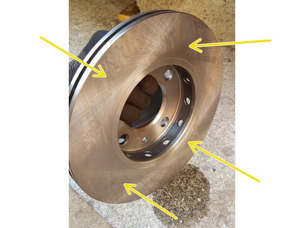
Pulvérisez du nettoyant-frein sur les 2 faces du disque.
-
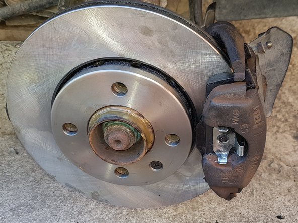
Repositionnez le disque et fixez-le avec la petite vis fournie avec le disque neuf.
-
Repositionnez les plaquettes dans l'étrier en les mettant aux bonnes places puis fixez l'étrier avec les 2 vis.
-
-
-
Voici l'anti-bruits que j'utilise et qui est particulièrement efficace.
-
Une fois le remontage terminé, enfoncez plusieurs fois la pédale de frein pour mettre les plaquettes en appui contre les disques.
-
Vérifiez le niveau de liquide de frein dans le bocal.
-
Pour le rodage des plaquettes neuves, ne pas effectuer de freinages brusques lors des premiers 200 kms.
-
L'efficacité des premiers freinages peut être réduite.
-


Annulation : je n'ai pas terminé ce tutoriel.
3 autres ont terminé cette réparation.
3 commentaires
Bonjour, il me semble que une fois tout remonter une géométrie est nécessaire non?
meiersteph - Résolu à la publication Réponse
très clair, bien étayé par les images.
Merci à l’auteur.
Jean-Luc (un bricoleur)
jean-luc.mottet - Résolu à la publication Réponse