


Difficulté
Très difficile
Étapes
46
Temps nécessaire
04:00:00

Ce tutoriel a été créé par la communauté
User contributed
Introduction
Tutoriel réalisé sur Peugeot 205 essence (1.4i - TU3M)
Pièces
-
-
Dans un premier temps, vidanger le circuit de refroidissement, pour se faire, ouvrez les différents bouchons/vis de purge
-
Ouvrez le bocal de liquide de refroidissement
-
Ouvrez le bouchon du radiateur
-
-
-
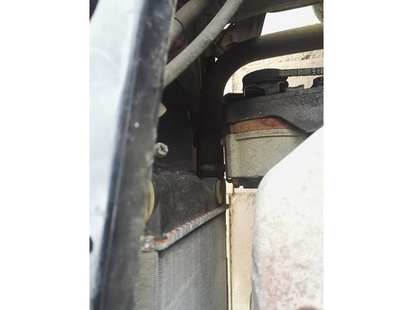
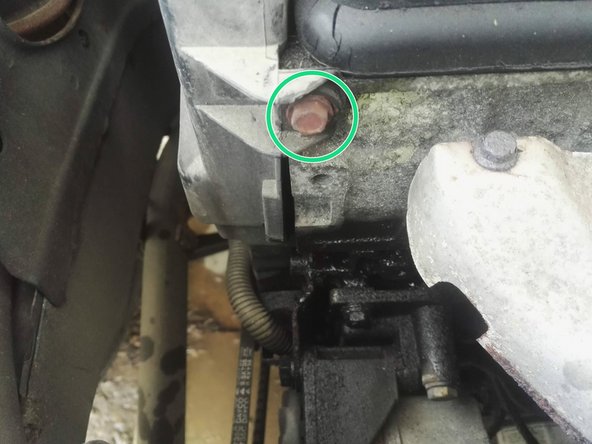
Ouvrez la vis de purge du circuit de chauffage
-
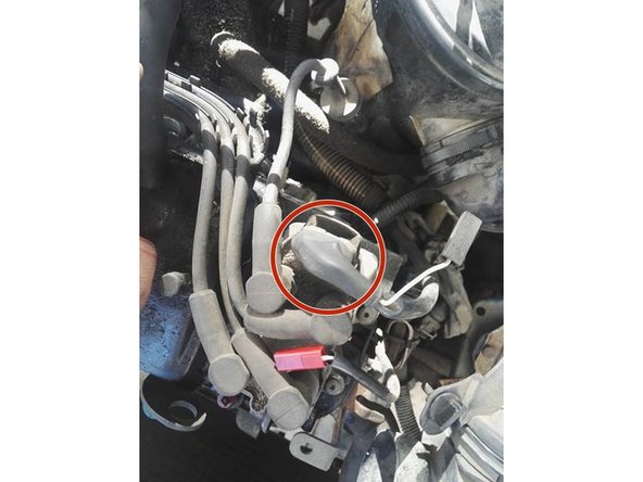
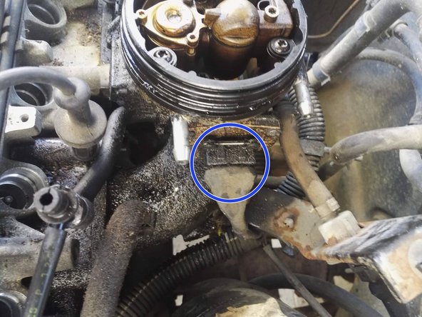
Ouvrez la vis de purge du boitier du calorstat
-
-
-
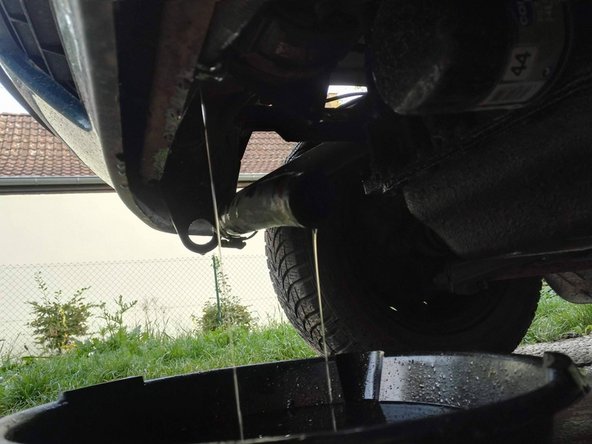
Placez une bassine sous la durite inférieure du radiateur, puis déconnectez la
-
Une fois tout le liquide évacué, refermez les différentes purges/bouchons et reconnecter la durite inférieure
-
-
-
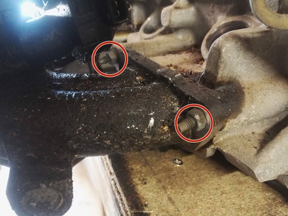
Dévisser les 2 vis de fixations du carter de distribution
-
-
-
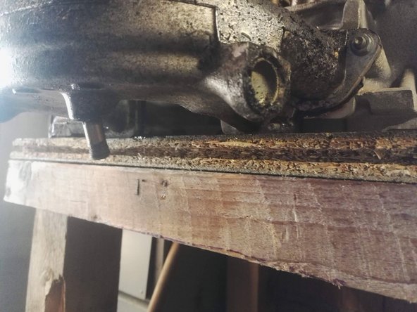
Retirez le carter en le tirant simplement vers le haut
-
-
-
Détacher la gaine électrique du carter
-
Dévisser les 3 vis de fixation du carter inférieur de distribution
-
-
-
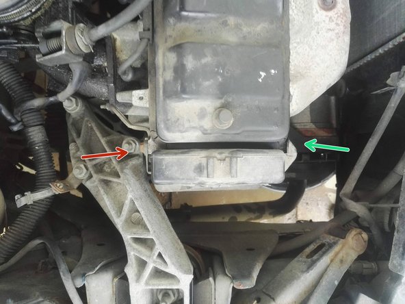
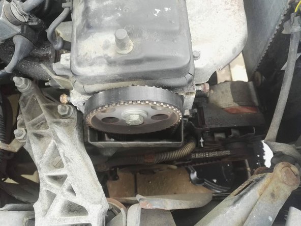
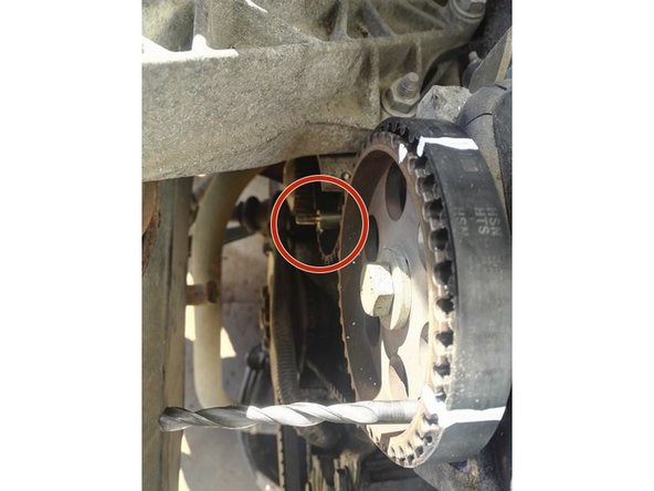
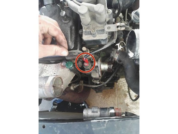
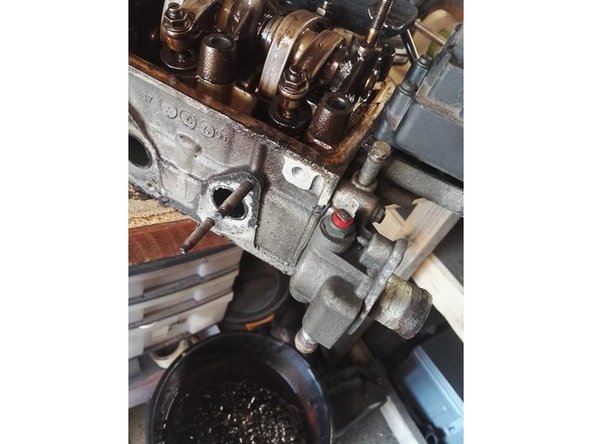
Aligner approximativement le trou dans la poulie d'arbre à came (rouge) au trou de pigeage dans la culasse (vert) (rester un peu avant)
-
Pour se faire, faire tourner le moteur à la main à l'aide d'une clé sur l'écrou de fixation de la poulie de vilebrequin en "serrant" l'écrou, le moteur va tourner.
-
-
-
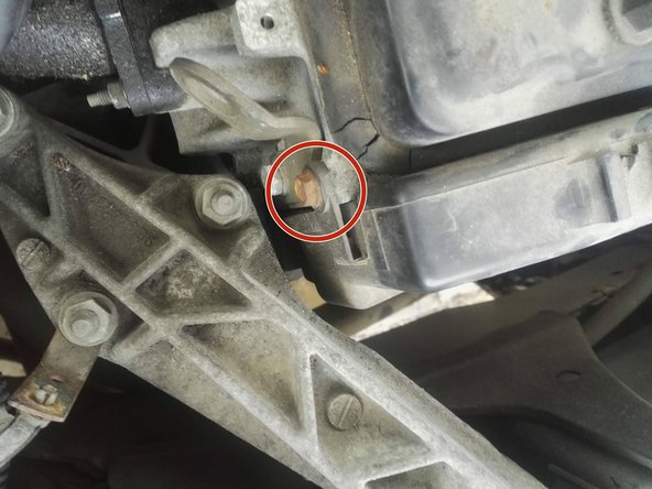
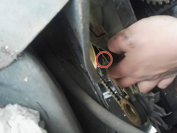
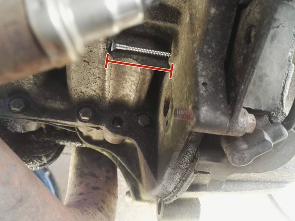
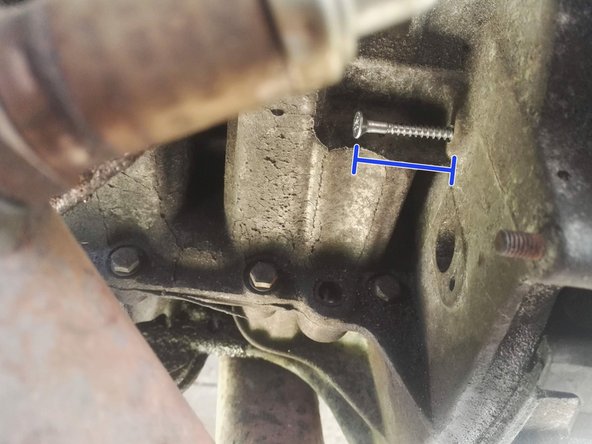
Une fois les 2 trous presque alignés, préangager la pige dans le trou du volant moteur (ici une vis de ø6mm)
-
En continuant d'essayer d'enfoncer la pige, faire doucement tourner le moteur jusqu'à ce que la pige s'enfonce et que le moteur se retrouve bloqué
-
-
-
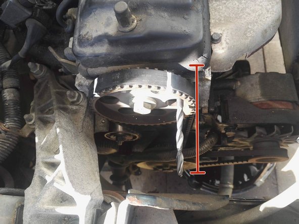
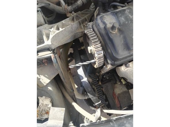
Une fois le volant moteur bloqué, les trous de pigeages de la poulie d'arbre à came doivent être alignés, mettre également la pige en place (foret ø8mm ici)
-
Vous pouvez également marquer la courroie/poulie au cas où votre pige viendrait à se retirer
-
-
-
Dévissez et déposez le galet tendeur (Déjà déposé sur la photo)
-
Retirez la courroie
-
-
-
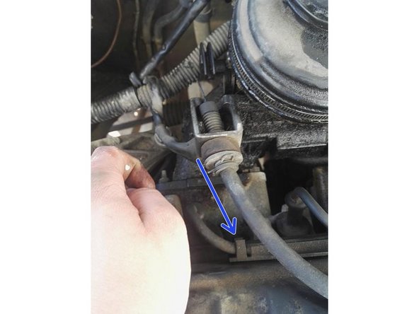
Déposez le câble d'accélérateur en basculant le papillon (Comme si vous appuyez sur la pédale) et simplement le glisser hors de son logement
-
Tirez ensuite sur la gaine pour la dégager du support
-
-
-
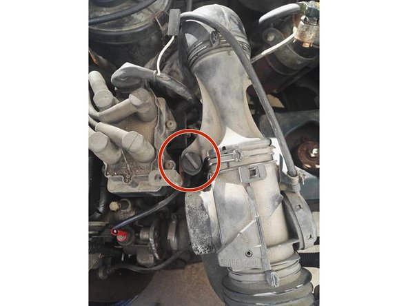
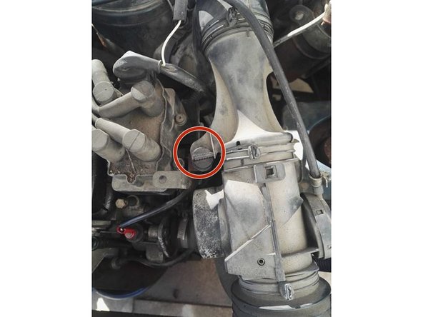
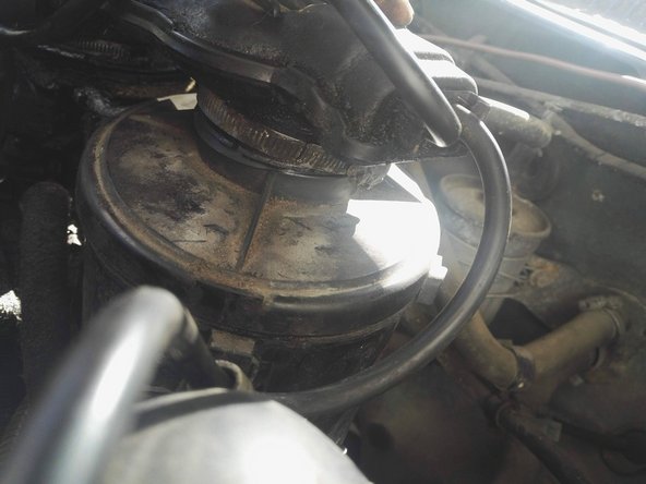
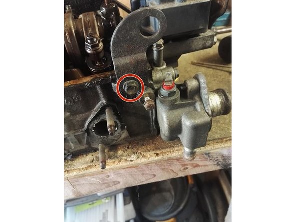
Tournez la vis en plastique d'un quart de tour et dégagez là de son logement
-
-
-
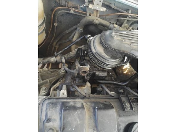
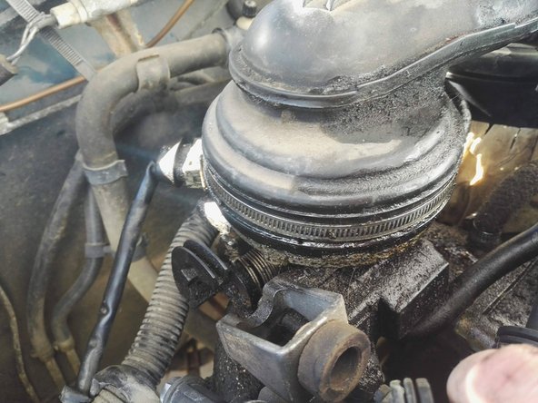
Ouvrir les 2 colliers de fixation et désolidariser le boitier d'admission d'air
-
-
-
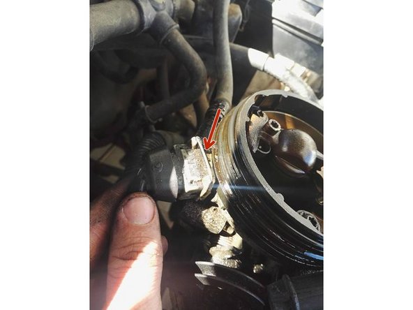
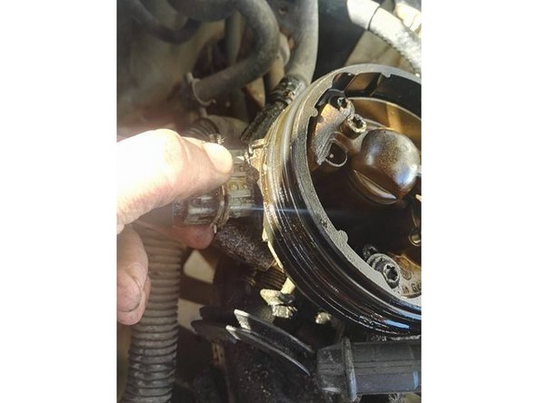
Débranchez les connectiques du boitier d'injection
-
Pour débrancher les fiches électriques, appuyez sur la languette métallique puis tirez sur la fiche
-
-
-
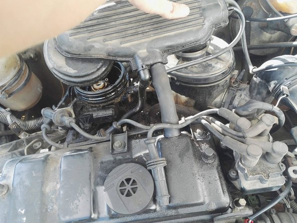
Débranchez le connecteur du boitier d'allumage
-
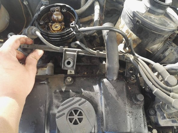
Débranchez les fils de bougies et déposer la rampe d'attache de fils de bougies
-
-
-
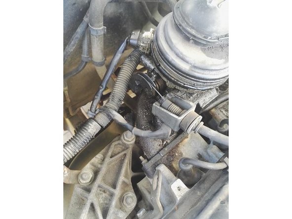
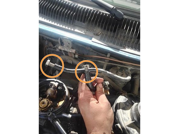
Débranchez les 2 durites d'essence allant au boitier d'injection
-
Bouchez les avec des vis
-
Débranchez également le connecteur électrique
-
-
-
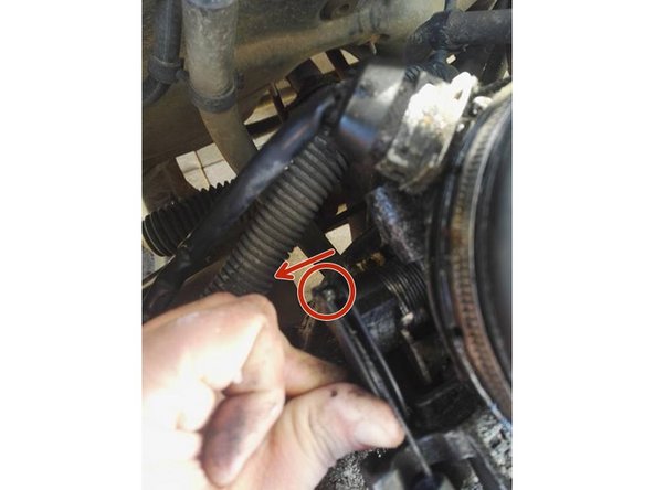
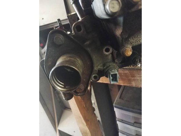
Libérez la durite du radiateur au niveau du boitier du calorstat
-
-
-
Déposez également la durite de chauffage au niveau du boitier du calorstat
-
-
-
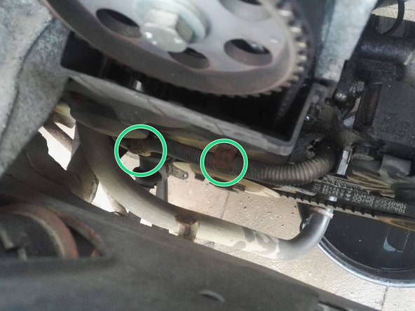
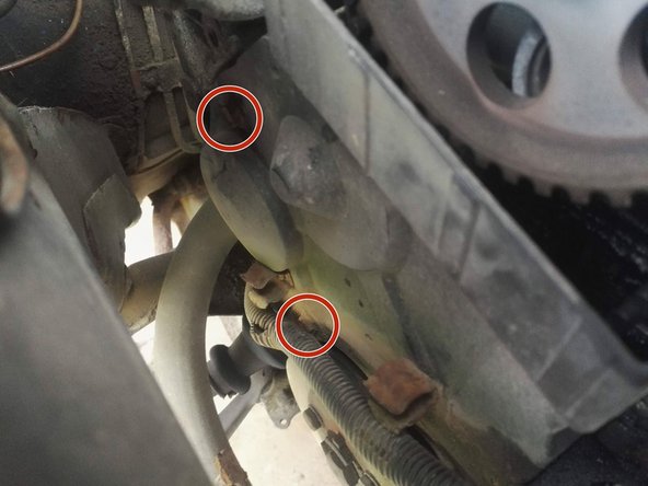
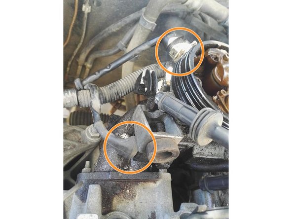
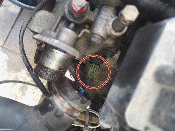
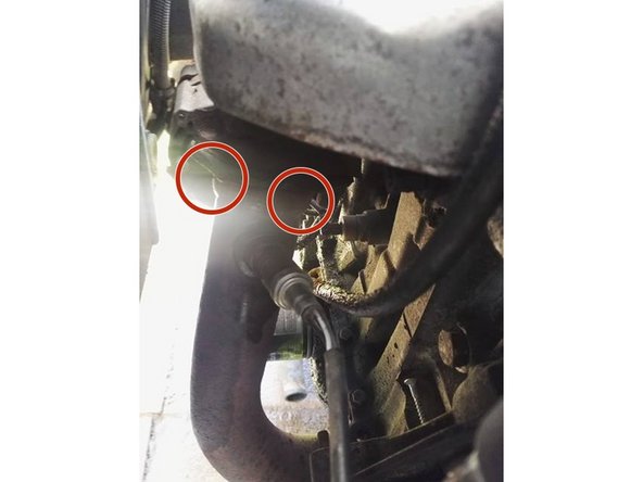
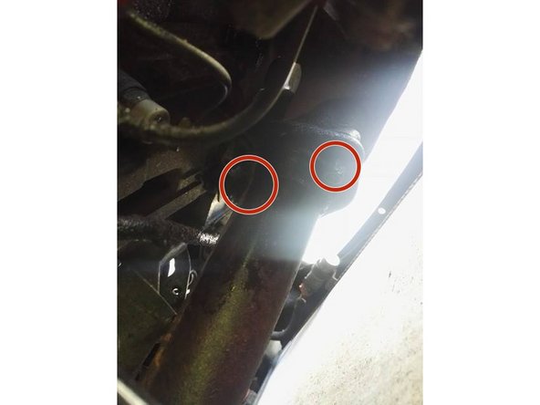
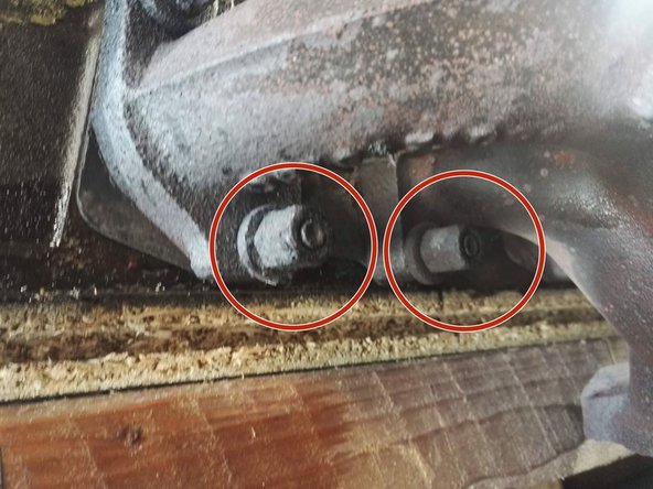
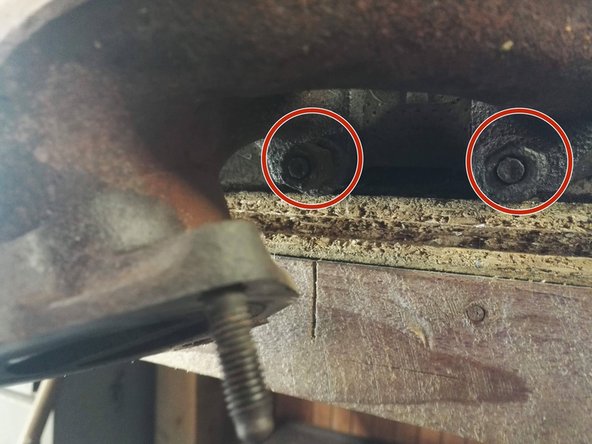
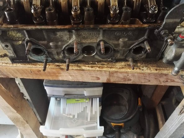
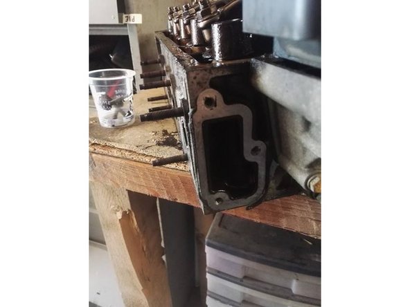
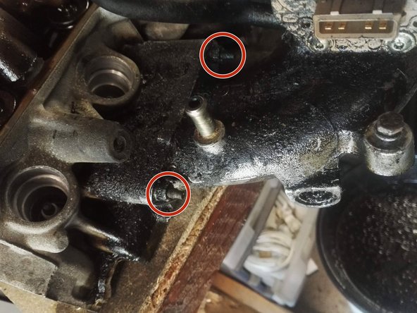
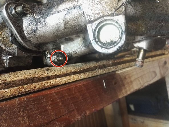
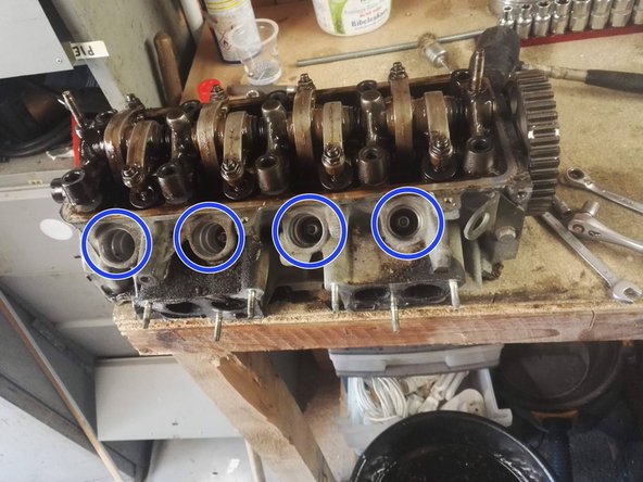
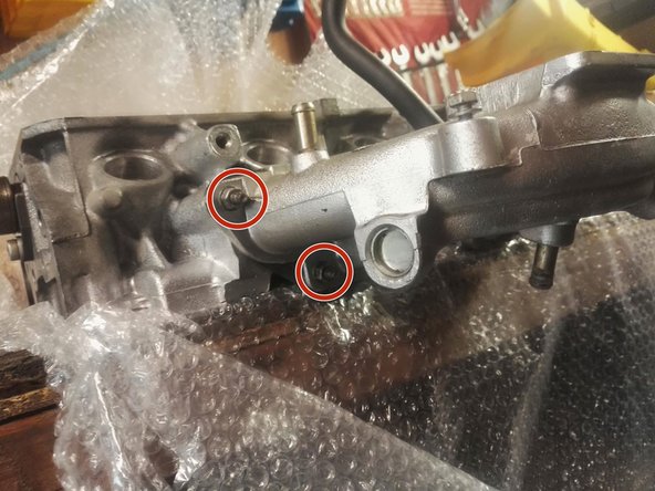
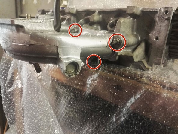
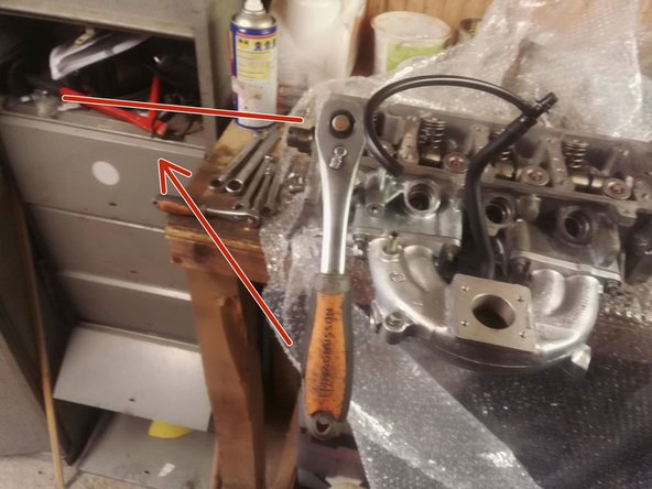
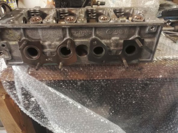
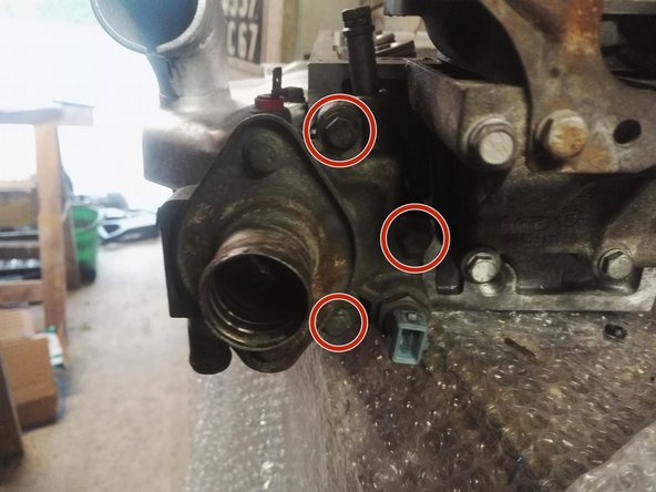
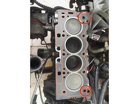
Ouvrir les 3écrous de fixation de la ligne d'échappement.
-
3eme photo après déculassage pour vous aidez à repérer les positions des 3 écrous plus facilement
-
-
-
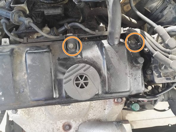
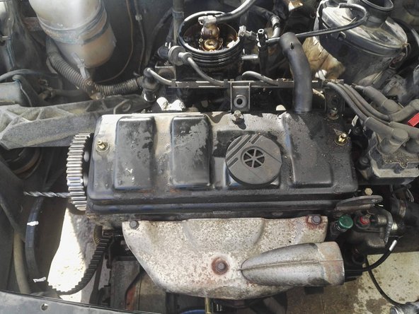
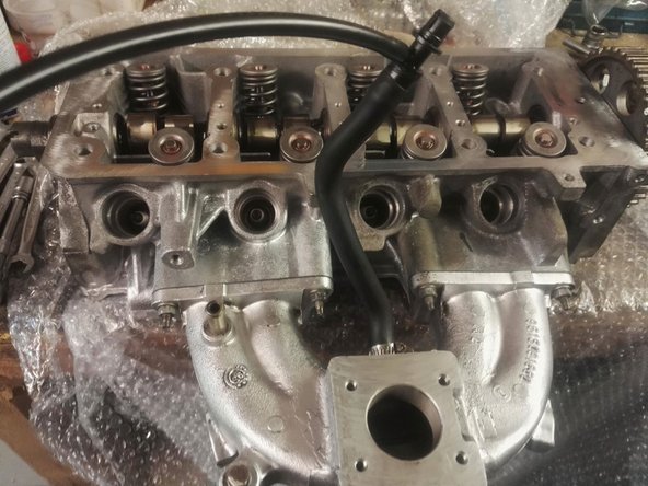
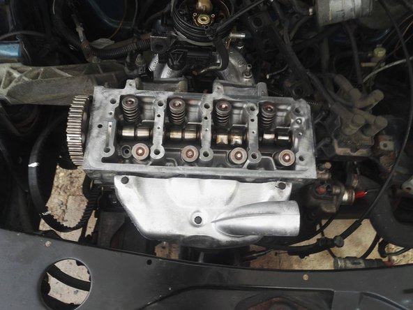
Dévissez les 2 écrous de fixation du cache culbuteur
-
Déposez le cache culbuteur
-
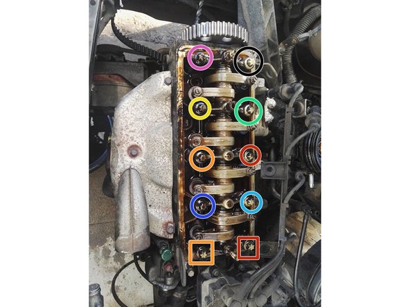
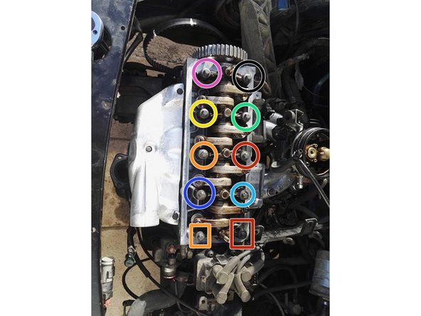
Dévissez les vis de culasse en escargot (Cercle rouge => orange => jaune => vert => bleu ciel => bleu foncé => rose => noir => carré rouge => carré orange
-
-
-
Retirez les vis
-
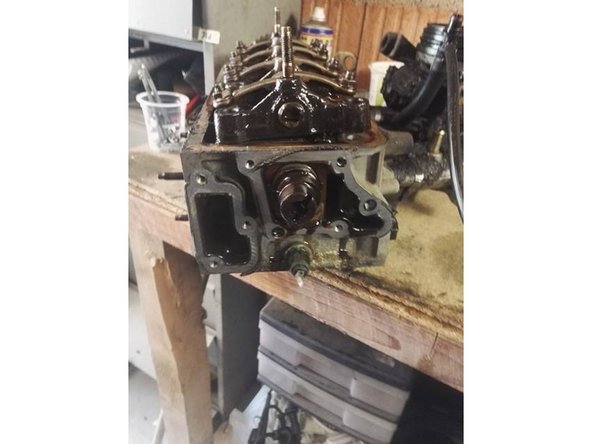
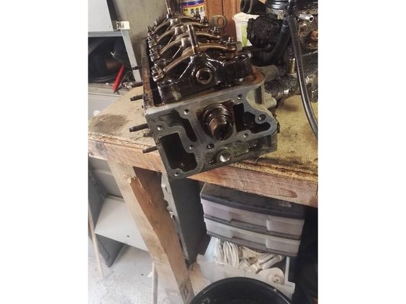
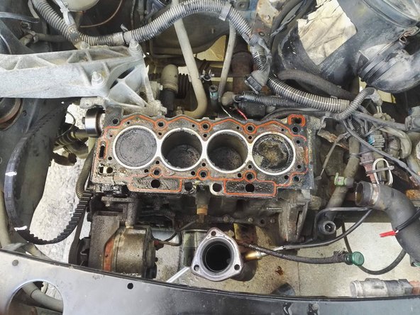
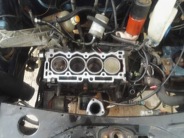
Basculez légèrement la culasse, vérifiez que rien n'est oublié (Faisceau/élément mécanique) et levez la pour la déposer. Posez là ensuite à plat en faisant attention au plan de joint
-
-
-
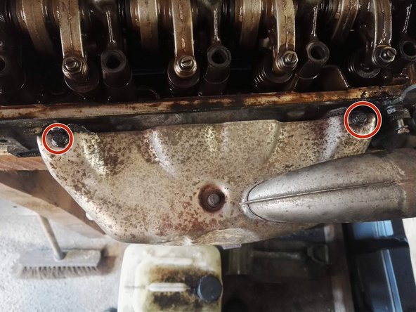
Dévissez les 2 vis de fixation du pare chaleur et le déposer
-
-
-
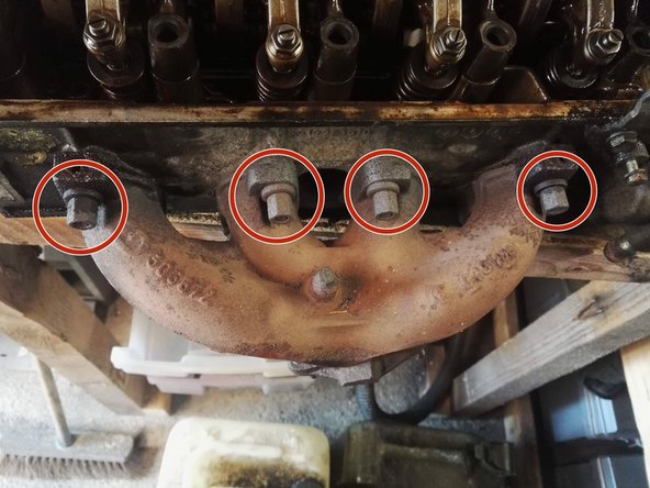
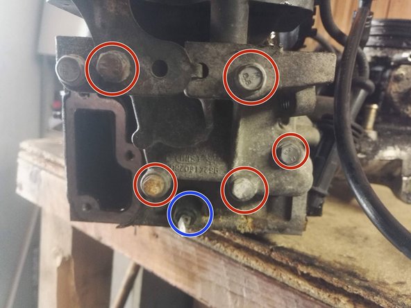
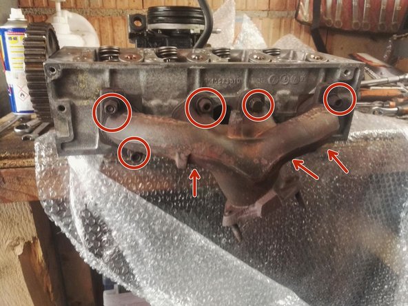
Dévissez les écrous de fixation du collecteur d'échappement
-
-
-
Dévissez les vis de fixation du module d'allumage
-
Retirez le module d'allumage
-
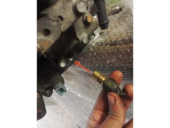
Dévissez également la sonde de température culasse
-
Nettoyez les plans de joint
-
-
-
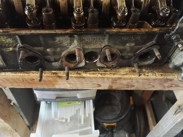
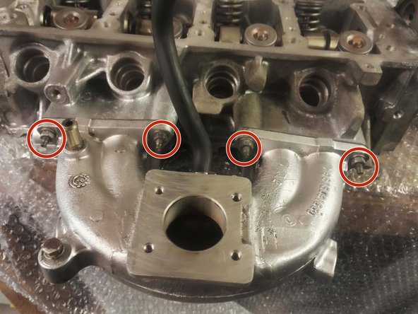
Dévissez les écrous de fixation de la pipe d'admission
-
-
-
Dévissez les écrous de fixation de la pipe d'admission
-
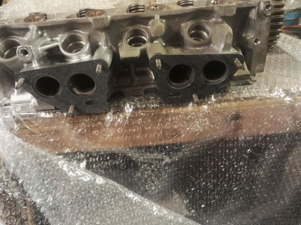
Déposez la pipe d'admission et nettoyer le plan de joint
-
Devissez et retirez également les 4 bougies
-
-
-
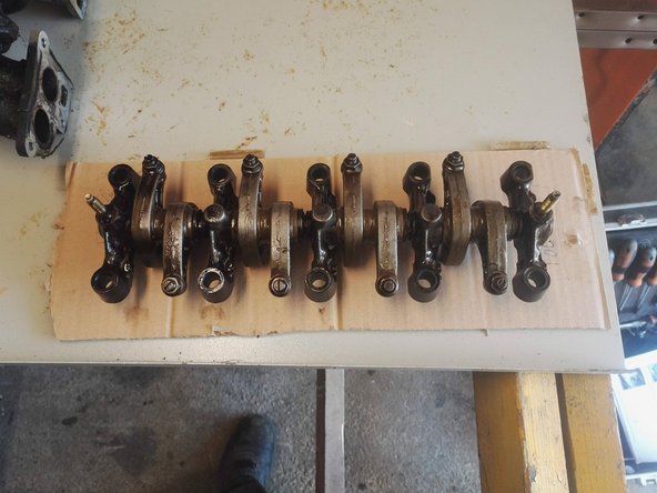
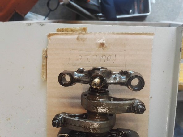
Déposez la rampe de culbuteur et repérez son sens de montage (à l'aide d'un carton par exemple)
-
La culasse est désormais à nue, vous pouvez la déposer chez le rectifieur (FORTEMENT conseillé de la faire rectifier + éprouver)
-
-
-
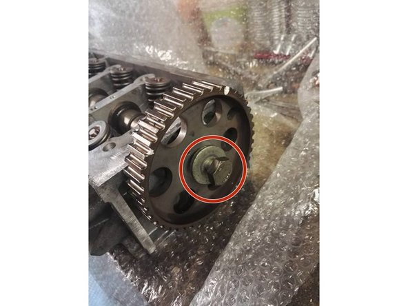
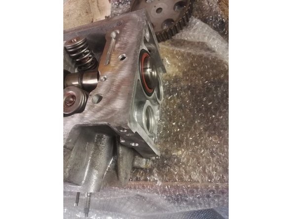
Dévissez la vis de la poulie d'arbre à came, retirez la pige et retirez la poulie
-
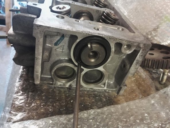
Extraire l'ancien joint en s'aidant d'un tournevis
-
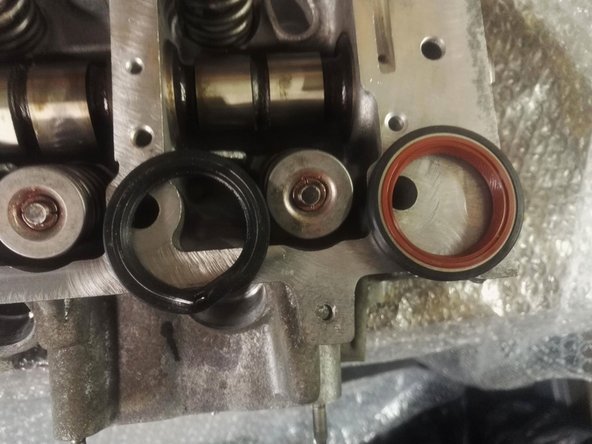
Comparez le nouveau joint avec l'ancien
-
-
-
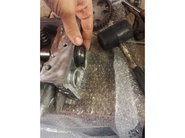
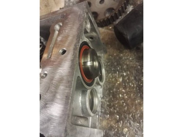
Insérez le nouveau joint en le rentrant à la main au plus loin
-
Placez l'ancien joint devant et tapez avec un maillet caoutchouc pour enfoncer complètement le nouveau joint
-
-
-
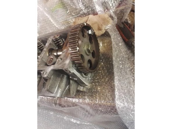
Remontez la poulie d'AAC et remettre la pige en place
-
-
-
Mettre en place les nouveaux joints
-
Mettre en place la pipe d'admission (Module d'injection déposé, mais ce n'est pas obligatoire)
-
Serrez (progressivement) les écrous de fixation
-
-
-
Serrez (progressivement) les écrous de la pipe d'admission
-
-
-
Remettre les bougies en place, serrez d'abord à la main, puis terminez par un quart de tour au cliquet
-
Profitez en pour monter de nouvelles bougies
-
-
-
Mettre en place les nouveaux joints
-
Mettre en place le collecteur d'échappement et serrez progressivement les écrous de fixation
-
-
-
Nettoyez les plans de joints
-
Mettre de la pate à joint sur le module d'allumage
-
Serrez progressivement les vis de fixation
-
-
-
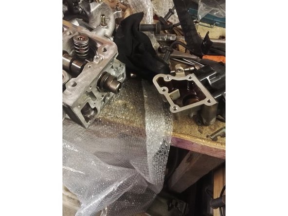
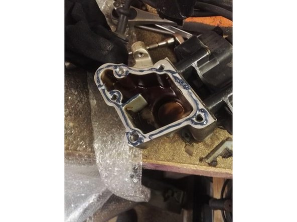
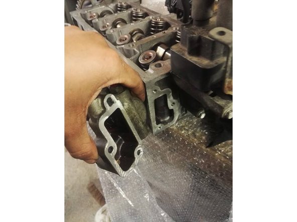
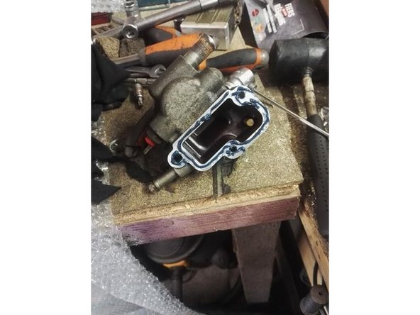
Nettoyez les plans de joint
-
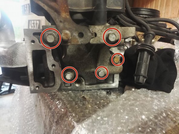
Mettre de la pâte à joint sur le boitier du calorstat
-
Serrez progressivement les vis de fixation
-
-
-
Resserez également la sonde de température de culasse
-
-
-
Retirez l'ancien joint
-
Nettoyez bien le plan de joint, il ne doit subsister aucun résidu !
-
Mettre en place le nouveau joint (bien s'assuré de la présence des 2 centreurs !)
-
-
-
Positionnez la culasse
-
Replacer la rampe de culbuteur
-
Placez les vis de culasse
-
-
-
Ordre de serrage pour toutes les étapes suivantes (serrage en escarogt) : Rond rouge => orange => jaune => vert => bleu clair => bleu foncé => rose => noir => carré rouge => carré orange
-
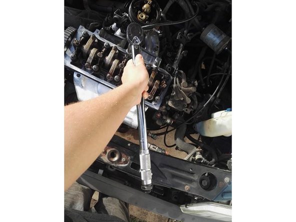
Effectuez un premier serrage à 20Nm
-
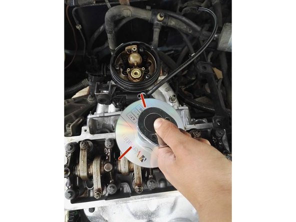
Effectuez un deuxième serrage à 120°
-
Utilisez un CD avec des repères à 120° si vous ne possédez pas de clé angulaire
-
Effectuez un troisième serrage à 120°
-
-
-
Procédez au remontage des différents éléments et reconnecter les différentes connectiques.
-
Reportez vous aux étapes 22 à 11
-
Réalisez une vidange du véhicule, avec remplacement du filtre à huile
-
Remplissez à nouveau, et purgez, le circuit de refroidissement
-
Il est recommandé d'effectuer un réglage du jeu des culbuteurs suite à cette opération.
-
Une fois que le moteur a chauffé une première fois, je vous conseille de déposer le cache culbuteur et de le nettoyer à nouveau (Présence d'un peu de mayonnaise)
-
Je préconise également une nouvelle vidange + purge du circuit de refroidissement après 500 kms environ à fin de bien nettoyer le circuit.
-


Annulation : je n'ai pas terminé ce tutoriel.
11 autres ont terminé cette réparation.
9 commentaires
Bonjour,
Normal que le joint de culasse est différent de celui d’origine ? il manque des trous de passage d’eau coté allumage
thieldamien - Résolu à la publication Réponse
Un grand merci à l’auteur de ce tuto. C’est pour nous une grande aide !
Il faudrait juste rajouter les couples de serrage, et préciser que lorsque l’on retire la culasse il faut faire des basculements avant-arrière, et pas soulever la culasse vers le haut au risque d’abimer les chemises de cylindre
enzo.gilbin - Résolu à la publication Réponse
Merci beaucoup, ce tuto est très bien fait et m’a été très utile, peut être rajouter l’ensemble des couples de serrage ,poulie ext. mais franchement c’est du très bon travail.
Bien cordialement
philippe lebon - Résolu à la publication Réponse
Bonjour,
Merci pour ce tutoriel bien détaillé.
Je voudrais demandé juste s’il n’y a pas un joint SPY coté allumage? Je ne le vois pas du tout et je me demande qu’est ce qui doit rendre étanche ce côté là? Juste le joint torique dans l’allumeur?
Merci de votre réponse.
Mohamed Najdat BEN BELGACEM - Résolu à la publication Réponse