


Difficulté
Modérée
Étapes
6
Temps nécessaire
00:45:00

Tutoriel complet
Ce tutoriel contribué par la communauté est complet et prêt pour l'examen de l'équipe Oscaro.

Ce tutoriel a été créé par la communauté
User contributed
Introduction
Ce tutoriel vous aide a effectuer la vidange du circuit de refroidissement sur C3 Picasso 1.4l vti 95cv
-
-
Munissez-vous de la documentation du véhicule et des outils nécessaires à l'opération sans oublier les équipements de protection (lunette, gants, etc).
-
-
-
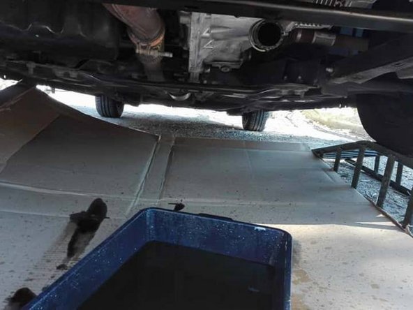
Sécuriser le véhicule (rampe, chandelle, etc), et protéger le sol.
-
-
-
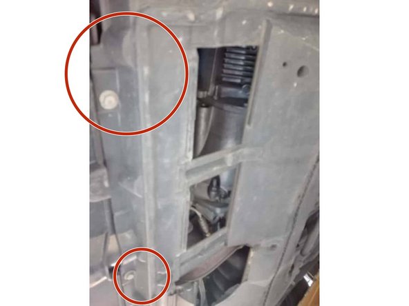
Déposer le carénage cinq boulons de 10 (rouge), deux clips ainsi que deux vis quart de tour (bleu).
-
-
-
A l'aide d'une pince à collier défaire la durite inférieure du radiateur.
-
Et laisser le liquide s’écouler dans le bac.
-
-
-
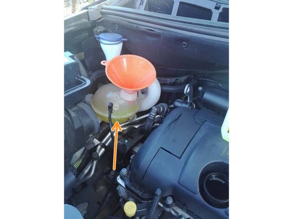
Retirer la durite de retour du vase et ouvrir le vase afin de faciliter l’écoulement et par la suite le remplissage.
-
D’après la RTA le véhicule n'est pas équipé de robinet de purge.
-
-
-
Replacer la durite et son collier (étape 4), puis la protection du carter inférieur (étape 3).
-
Rebrancher la durite du vase et remplir le circuit de refroidissement puis faire tourner le moteur vase ouvert afin d'évacuer l'air présent dans le circuit.
-
Une fois le véhicule descendu des cales refaire le niveau.
-


Annulation : je n'ai pas terminé ce tutoriel.
3 autres ont terminé cette réparation.
6 commentaires
Bonjour
Il y 2 vis de purge sur le circuit
La haute est située derrière le filtre à air et la basse est sous la reprise d’air. Pour l’enlever il d’abord retirer celle du turbo pour y accéder puis remettre temporairement celle du turbo en place pour éviter d’avoir du liquide dans le turbo car lorsque la purge est ouverte ça peut gicler (attention à faire moteur froid sinon risque de brûlure)
fredericgaidot - Résolu à la publication Réponse
Bonjour, d'après la RTA c'est la méthode officielle. Cela m'a aussi dérouté au premier abord. Ne pas oublier d'ouvrir le chauffage à fond pour purger celui-ci.
afeltra.ciro - Résolu à la publication Réponse
Malgré l’absence de vis de purge, ne devrait-il pas y avoir un moyen de purger le circuit pour enlever l’air qui s’y est engouffré lors de la vidange ?
mushroom25 - Résolu à la publication Réponse