


Introduction
Motorisation du véhicule 1.4 HDi 70 cv
-
-
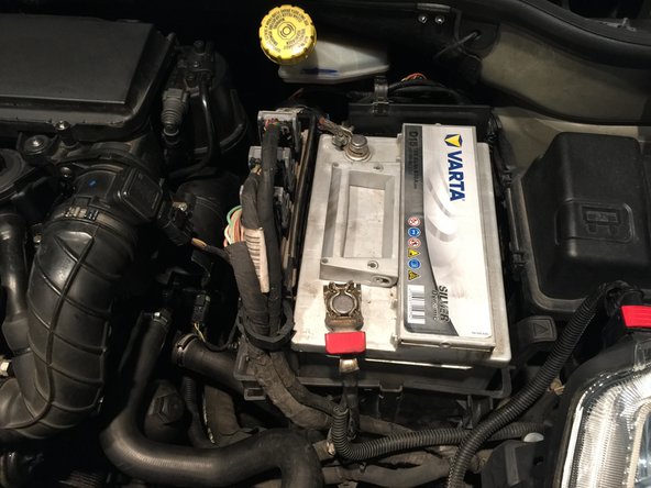
Le boitier du thermostat se trouve entre le moteur et la batterie.
-
Déposer le cache de protection de la conduite d'air.
-
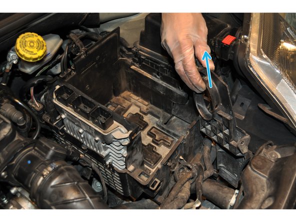
Déposer le cache moteur en tirant dessus vers le haut.
-
-
-
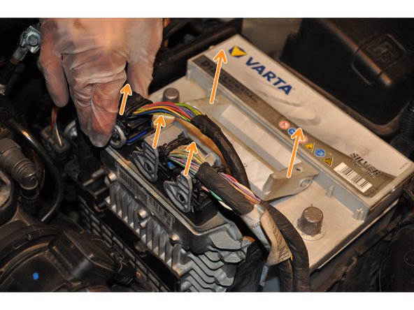
Déposer les caches de protection de la batterie.
-
Débrancher les cosses de la batterie.
-
-
-
Débrancher les trois connecteurs du calculateur et sortir la batterie de son logement par la poignée.
-
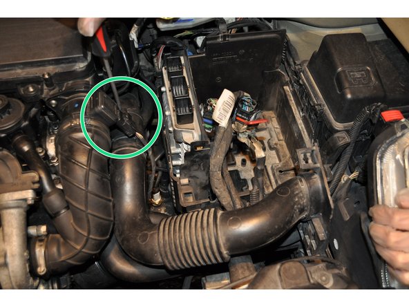
Déposer la vis de fixation de la conduite d'air.
-
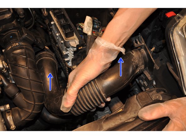
Déposer la conduite d'air.
-
-
-
Dégrafer les attaches des câbles sur le boitier
-
Déposer le support de la conduite d'air.
-
-
-
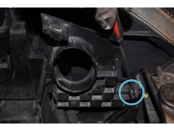
Déposer la cloison de protection pour accéder au calculateur de direction assistée.
-
Débrancher le second calculateur.
-
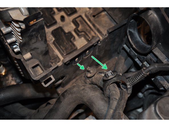
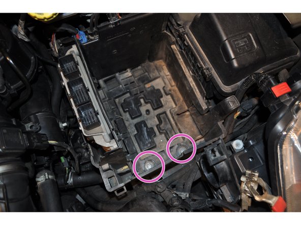
Utiliser une clé de 10 mm pour les deux vis de fixation au fond du boitier.
-
-
-
Sortir le support de la batterie en vérifiant qu'aucun câble n'est encore fixé dessus.
-
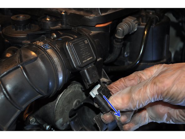
Débrancher le connecteur du débitmètre d'air.
-
Déposer la seconde partie de la conduite d'air.
-
-
-
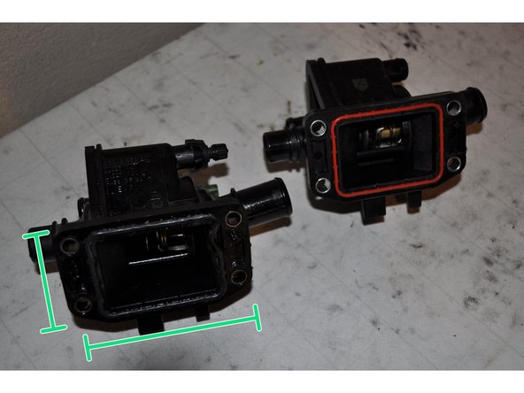
Le boitier est maintenant accessible. Il est fixé sur le moteur par 4 vis et relié à 3 durites.
-
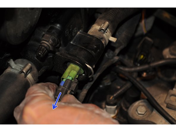
Débrancher le thermostat.
-
-
-
Ouvrir le bouchon du réservoir de liquide de refroidissement.
-
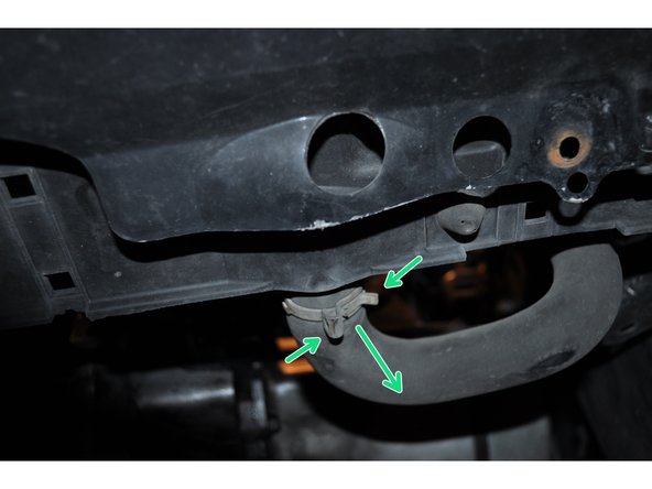
Desserrer le collier sur la durite basse du radiateur sous le véhicule afin de vidanger le circuit de liquide de refroidissement.
-
Récupérer le liquide de refroidissement dans une bassine.
-
-
-
Utiliser de la même manière une pince multiprise pour desserrer le collier de la durite haute du radiateur.
-
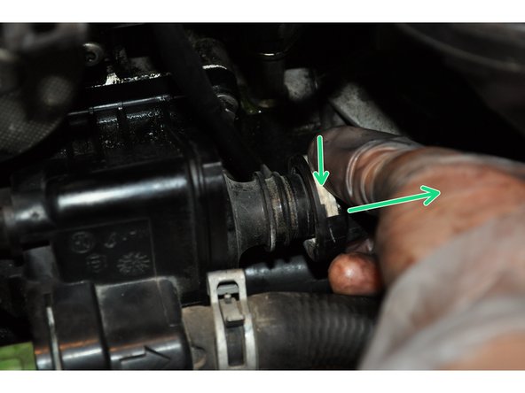
Presser la languette blanche pour débrancher la durite du circuit chauffage.
-
Déposer le collier de la troisième durite.
-
-
-
Déposer les 4 vis maintenant le boitier sur la culasse du moteur. Utiliser une douille de 8 mm.
-
-
-
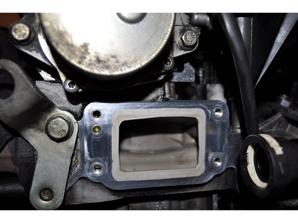
L'origine de la fuite est clairement visible.
-
Nettoyer la portée de joint sur le bloc moteur.
-
-
-
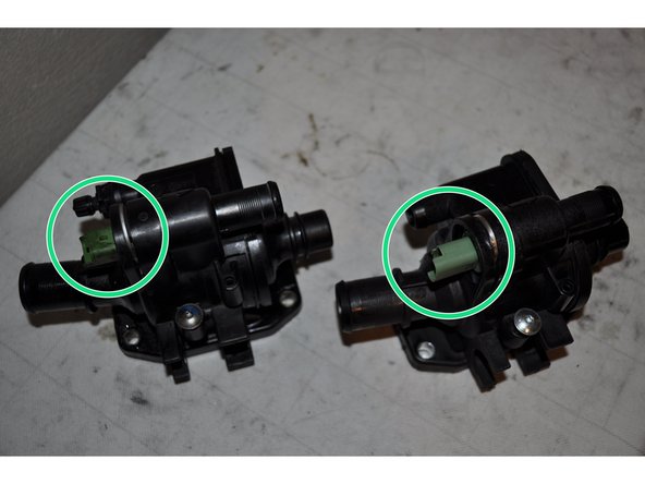
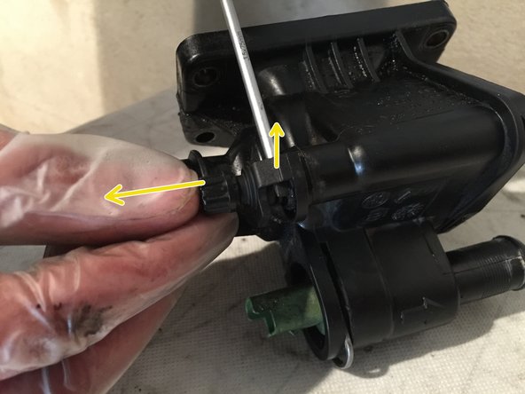
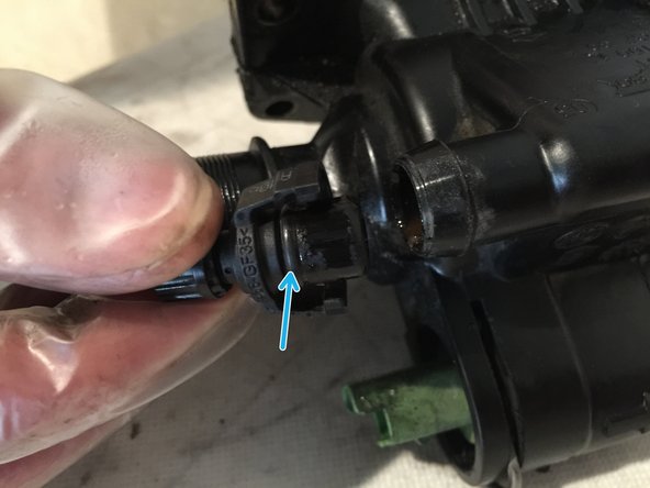
Déposer le purgeur de l'ancien boitier s'il n'est pas présent sur le nouveau.
-
Vérifier le joint d'étanchéité.
-
-
-
Mettre en place le boitier de thermostat sur le bloc moteur et serrer les vis.
-
Brancher la durite du circuit de chauffage.
-
Placer le purgeur sur le nouveau boitier.
-
-
-
Remettre en place les colliers de serrage des durites reliées au boitier. Ne pas oublier la durite basse du radiateur sous le véhicule.
-
Connecter le thermostat.
-
-
-
Repositionner la seconde partie de la conduite d'air sur la boite à air.
-
Remettre en place le support de la batterie ainsi que tous les branchements du calculateur. Puis la batterie.
-


Annulation : je n'ai pas terminé ce tutoriel.
6 autres ont terminé cette réparation.

8 commentaires
Merci à vous. Grâce à ce tuto j ai pu changer le calorstat sur 206 1,4 hdi de 2007. Pour moi la fuite venait d une des quatre vis desserrée. Ça s’en fait bien en prenant son temps. Pour le couple de serrage c est 10 Nw.
interminator2 - Résolu à la publication Réponse
La collerette du purgeur s’est cassée lors de la récupération sur l’ancien boîtier.
J’ai la référence “Norma RSS PA66-GF35”
Je n’arrive à trouver cette référence pour la remplacer.
Avez-vous une idée pour la trouver ?
pascal.jeunehomme@free.fr - 20/11/2021
pascal.jeunehomme - Résolu à la publication Réponse
Quelle est l'utilité de la vis torx que l'on voit sur la deuxième photo de l'étape 12 ? Sur l'ancien boîtier elle est vissée alors que sur la pièce neuve elle est présente mais complètement dévissée.
fr_laporte33 - Résolu à la publication Réponse