


Introduction
Motorisation du véhicule 1.4 HDi 70 cv
Les fuites de joints d’injecteurs sont un problème courant sur la motorisation 1.4 HDI de PSA
Les symptômes sont :
- une odeur de gaz d’échappement dans l’habitacle.
- un bruit caractéristique d'air comprimé s'échappant de la chambre de combustion.
- des fumées de gaz d’échappement dans le compartiment moteur.
-
-
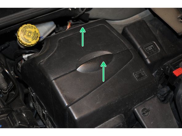
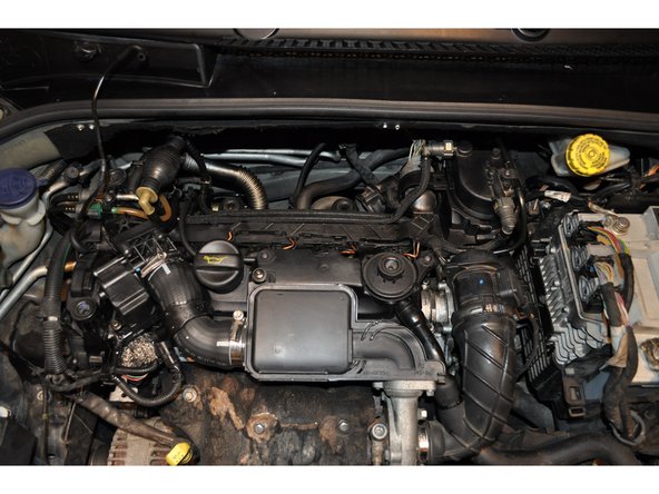
Ouvrir le capot et déposer l'enjoliveur moteur
-
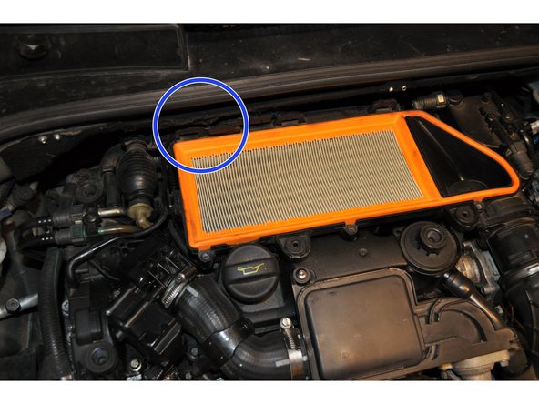
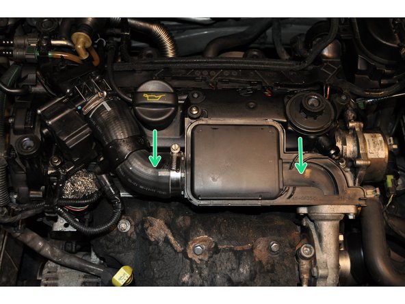
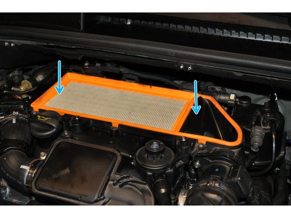
Les injecteurs se trouvent sous le boitier de filtre à air
-
Commencer par déposer le couvercle du boitier de filtre à air
-
-
-
Dévisser les 3 vis du couvercle avec une clé torx T20
-
Déposer le couvercle
-
Dévisser les 2 vis T20 de la boite à air
-
-
-
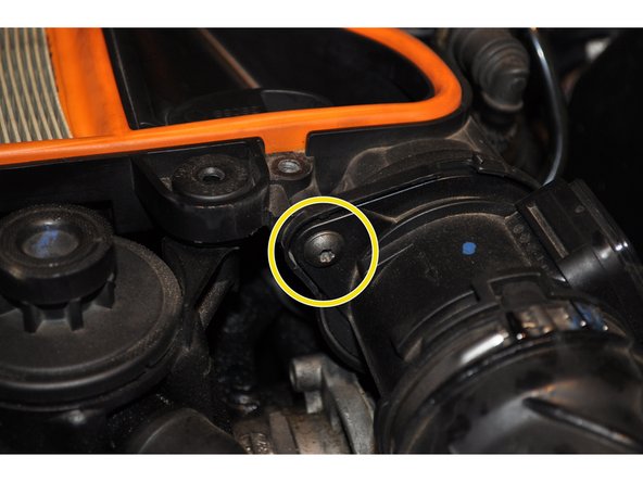
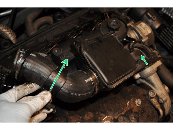
Sur la boite se trouve le débitmètre de masse d'air
-
Utiliser une clé torx T20 pour déposer les 2 vis de maintien
-
-
-
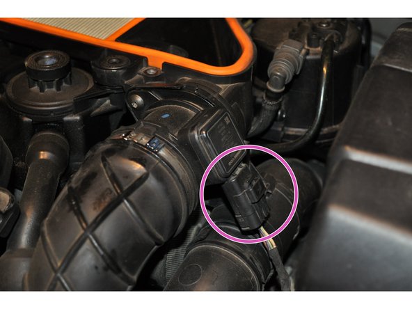
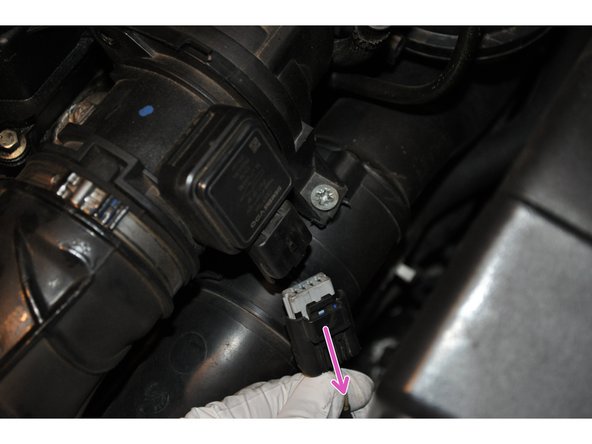
Débrancher le connecteur électrique du débitmètre de masse d'air
-
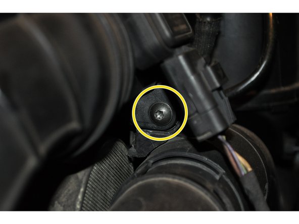
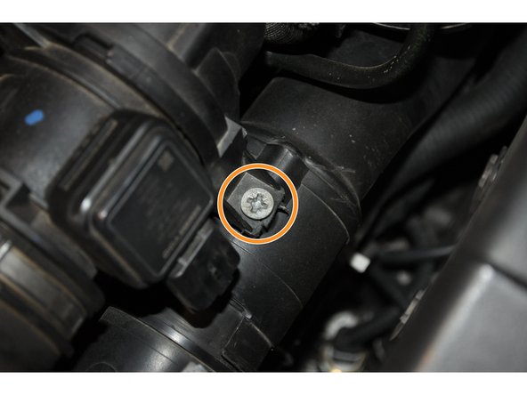
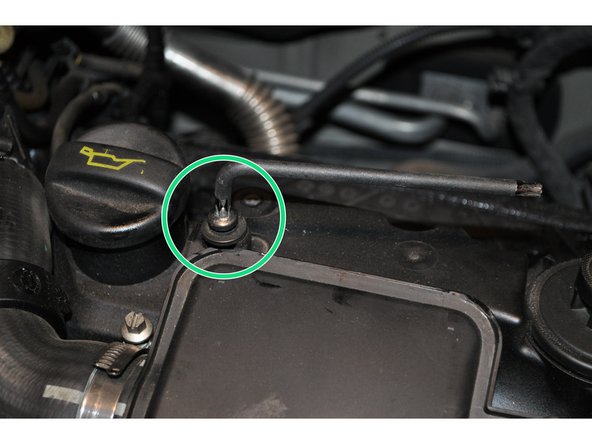
Dévisser la fixation de la conduite d'air
-
-
-
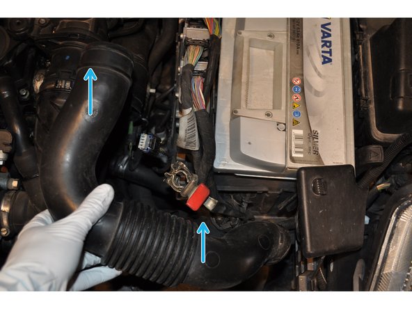
Déposer la conduite d'air
-
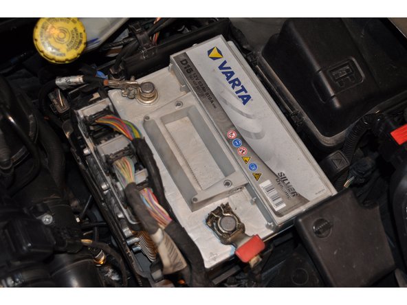
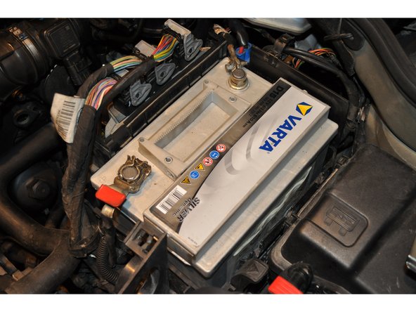
Débrancher la batterie avant d'intervenir sur le système électrique, par sécurité et pour ne pas avoir de message d'erreur au redémarrage du véhicule
-
-
-
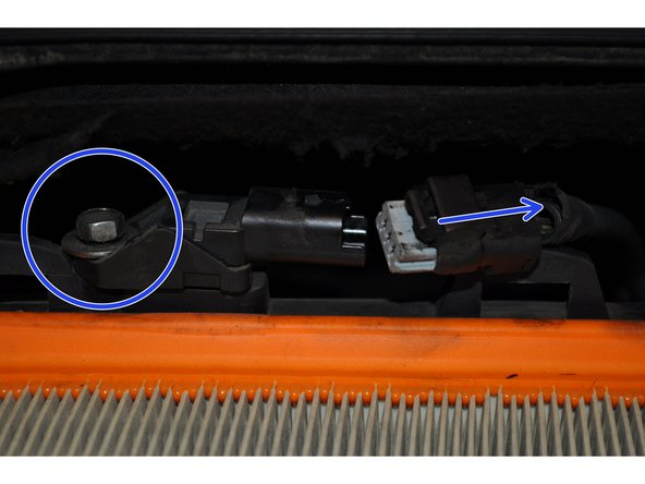
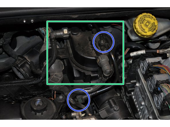
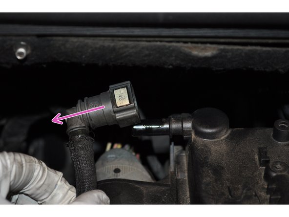
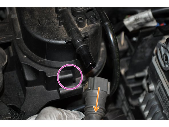
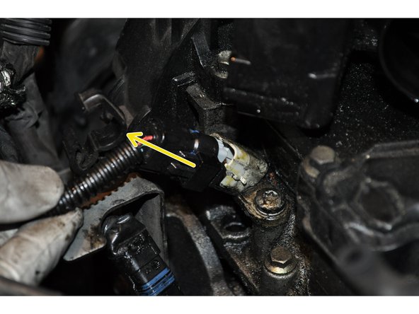
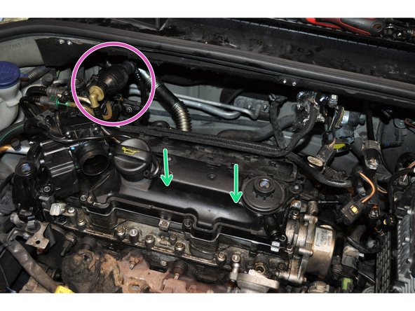
Déconnecter le capteur de pression d'air d’admission situé sous la baie du pare brise
-
Utiliser une clé de 10
-
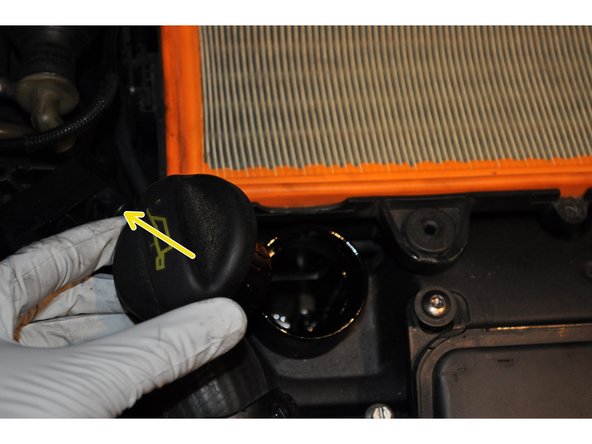
Enlever provisoirement le bouchon de remplissage d'huile pour faciliter la dépose de la boite à air
-
-
-
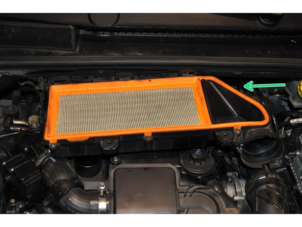
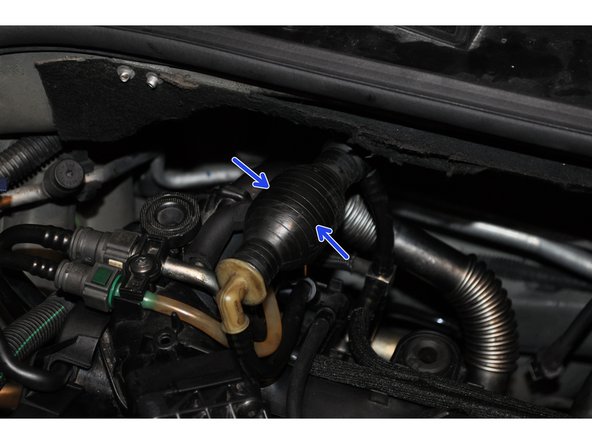
La seconde moitié de la conduite d'air est connectée à l’arrière de la boite à air. Passer la main derrière pour la déboîter
-
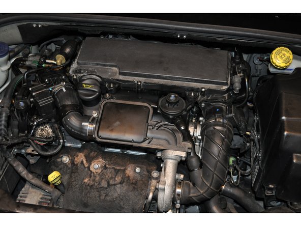
Sortir précautionneusement la boite à air de son emplacement.
-
-
-
Il faut ensuite déposer les différents éléments d'admission d'air
-
-
-
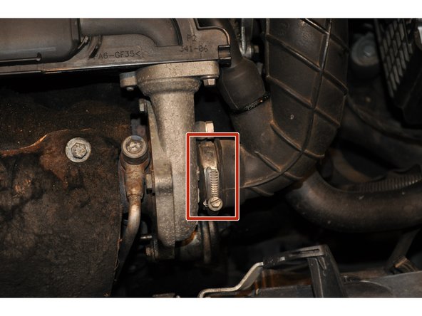
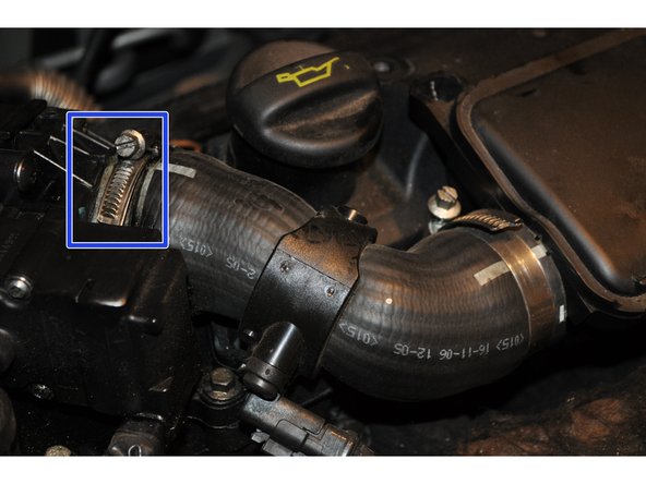
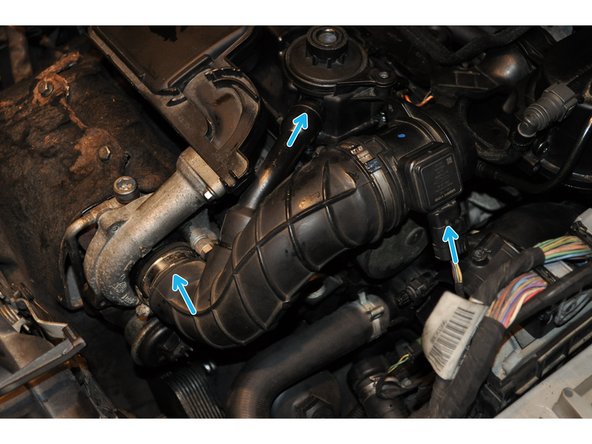
Déposer le collier maintenant la conduite sur le turbocompresseur à l'aide d'un tournevis plat
-
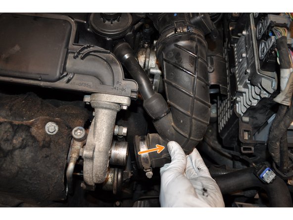
Déboîter la conduite et tirer légèrement pour enlever la seconde petite conduite d'air
-
-
-
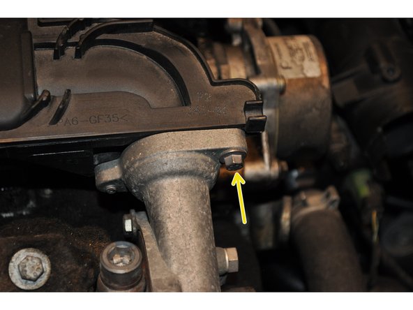
Déposer la vis de 8 mm entre le turbocompresseur et le résonateur d'air
-
Dévisser avec une clé torx T30 la fixation du résonateur sur le cache culbuteurs
-
Déposer le collier entre le résonateur et le cache culbuteurs
-
-
-
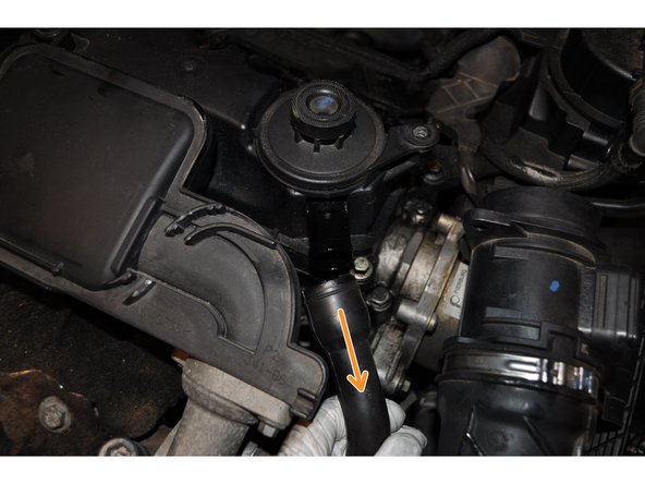
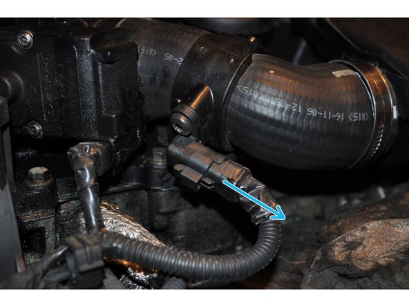
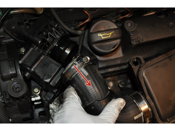
Débrancher le capteur de température d'air d'admission
-
Enlever d'abord la conduite
-
Puis faire pivoter l'ensemble pour le déposer
-
-
-
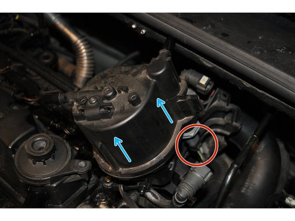
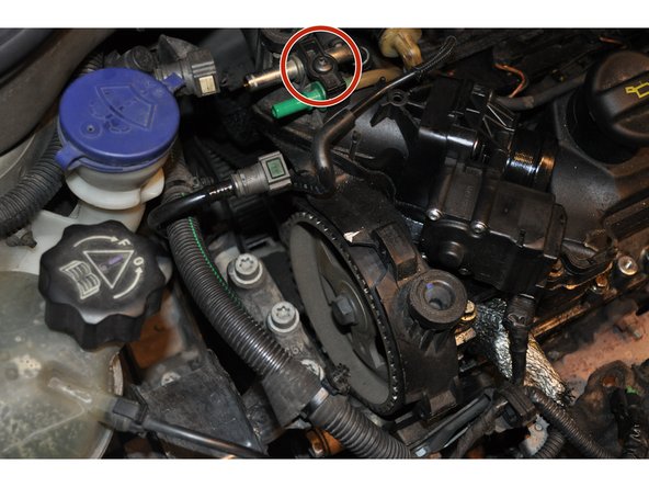
Continuer en déposant le circuit de carburant
-
Commencer par le filtre à gasoil
-
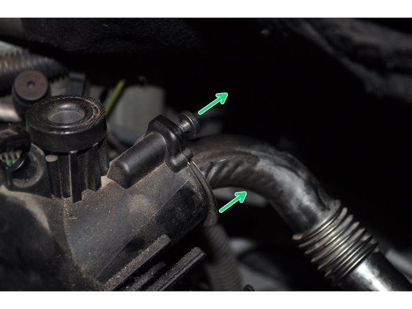
Dévisser la bride de la conduite d'air de dépression fixée sur le dessus du filtre
-
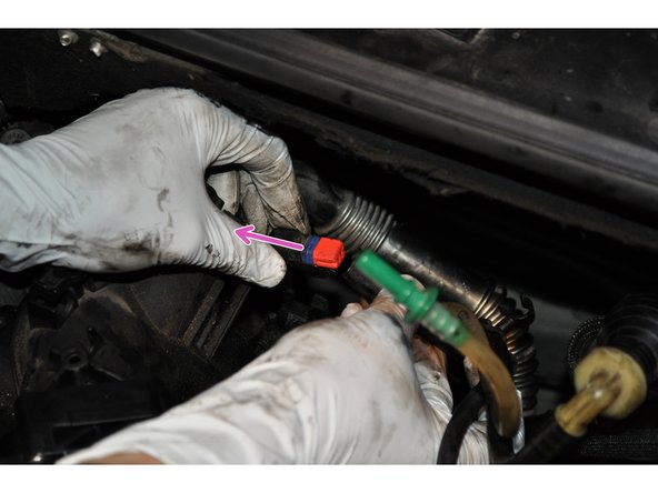
Débrancher la première durite du filtre
-
-
-
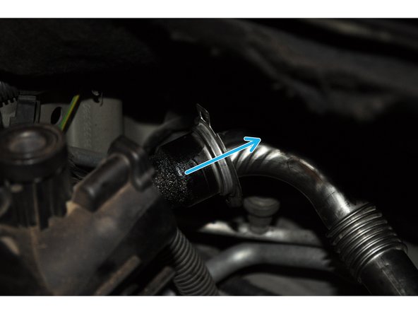
Puis débrancher la seconde durite du filtre à gasoil
-
Dévisser la vis de maintient du filtre sur son support avec une clé torx T20
-
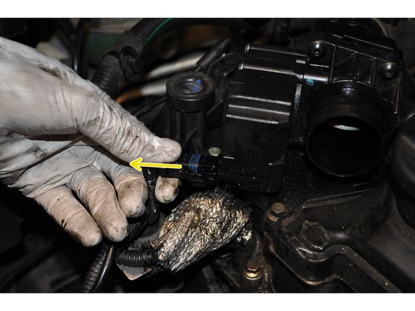
Déposer doucement le filtre de son support et débrancher le connecteur électrique qui se trouve en dessous
-
-
-
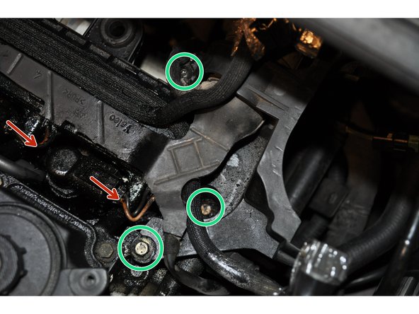
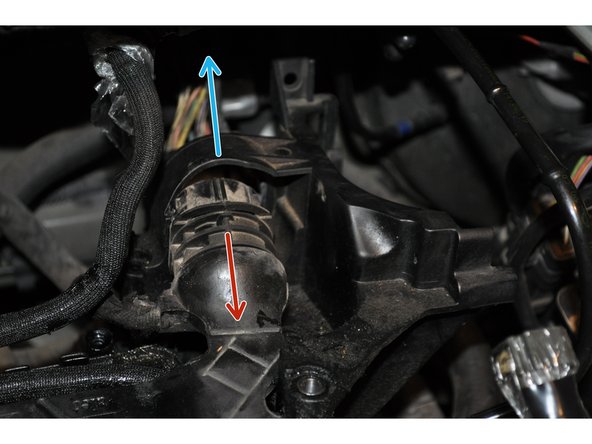
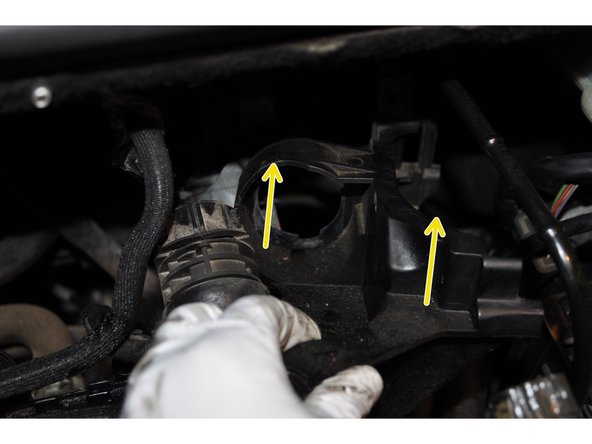
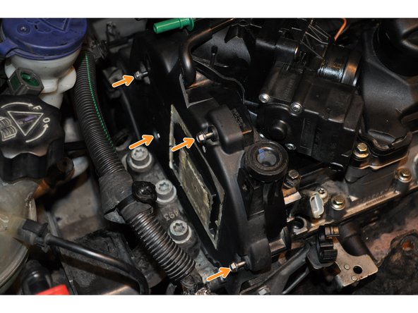
Le support du filtre à gasoil est fixé en 3 points. Utiliser une douille de 8 mm avec une rallonge et clé torx T30
-
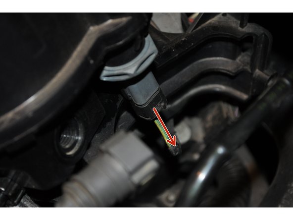
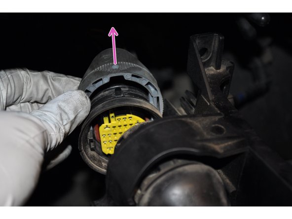
Déconnecter les 4 fiches électriques des injecteurs
-
Le faisceau électrique des injecteurs passe à travers le support
-
Soulever la bague grise pour déconnecter le faisceau
-
-
-
Séparer le support et le câblage électrique des injecteurs
-
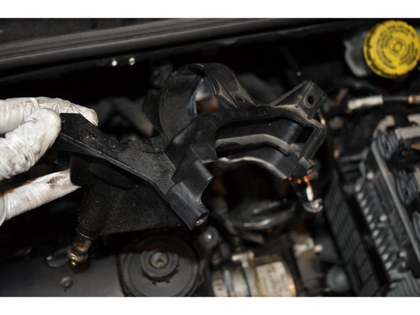
Déposer le support de filtre à gasoil
-
-
-
A gauche du moteur se trouve le carter supérieur de la courroie de distribution fixé sur le cache culbuteurs
-
Déposer les 5 vis de fixation avec une douille de 7 mm
-
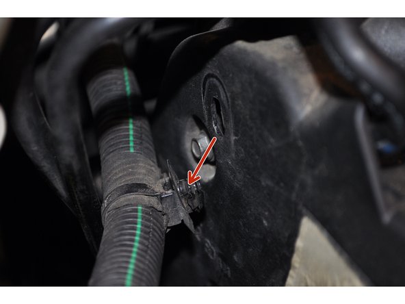
Plusieurs éléments sont positionnés sur le carter. Une gaine de câbles électrique est maintenue par une agrafe plastique
-
-
-
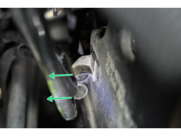
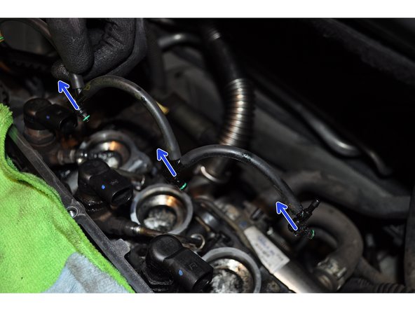
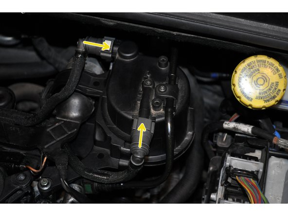
Les tuyaux d'alimentation de gasoil sont également fixés sur le carter
-
Déconnecter les durites de gasoil
-
-
-
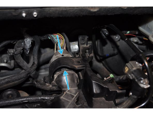
Déposer le carter supérieur de la courroie de distribution
-
Dévisser la bride des durites sur le cache culbuteurs avec une clé torx T30
-
-
-
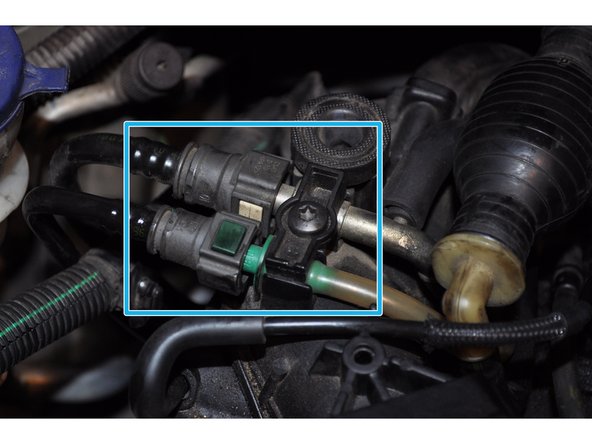
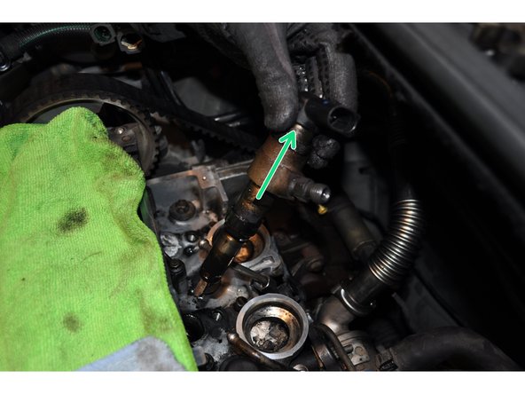
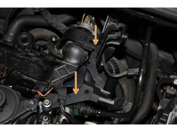
Le faisceau de tuyau est attaché sur le collecteur d'air. Utiliser un tournevis plat pour le déclipsser
-
Déconnecter la fiche électrique
-
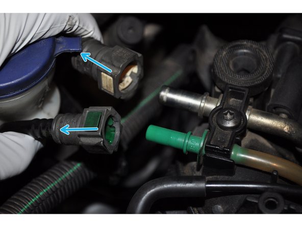
Déconnecter les tuyaux d’alimentation de gasoil
-
Vérifier que plus rien n'est connecté et déposer le faisceau complet.
-
-
-
Le système de recyclage des gaz d’échappements est fixé sur le collecteur d'air d'admission
-
Utiliser une clé torx T30 sur les deux vis de fixation
-
Séparer la conduite de la vanne EGR
-
-
-
Déconnecter les deux derniers capteurs
-
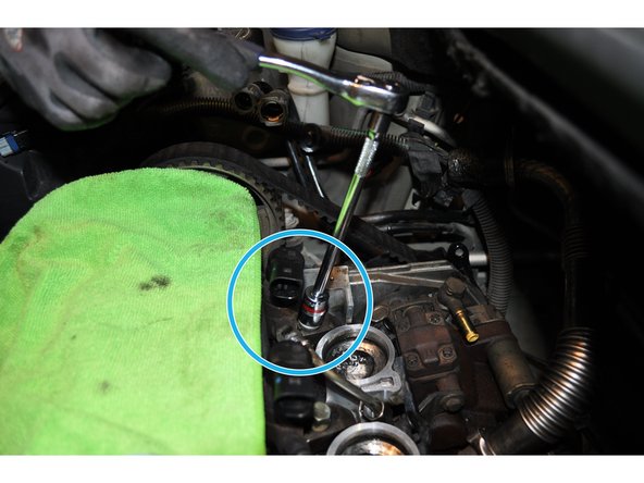
Déposer les 8 vis sur le dessus du cache culbuteurs avec une douille de 8 mm
-
Et les 2 vis de 10 mm dessous le collecteur d'air. A l’aplomb des support de la boite à air
-
-
-
Vérifier que plus rien n'est encore fixé sur le cache culbuteurs
-
Tirer vers le haut pour le déposer
-
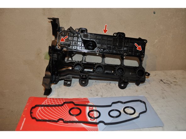
Enlever les 4 joints torique du collecteur d'air d'admission
-
-
-
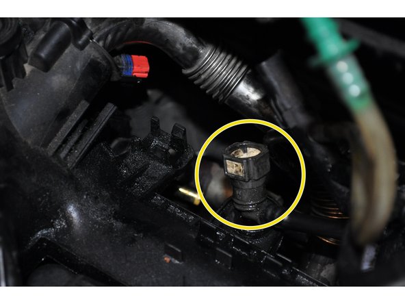
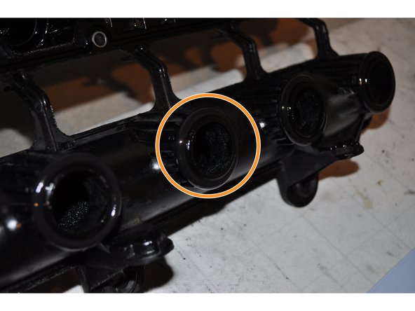
La fuite provient du joint d'étanchéité de cet injecteur
-
Protéger soigneusement le couvre culasse et boucher les orifices du collecteur d'admission d'air
-
Nettoyer au maximum avec un dégraissant avant de retirer les injecteurs
-
-
-
Même si la fuite provient d'un seul injecteur, il est essentiel de déposer les 4 injecteurs afin de remplacer les 4 joints d’étanchéité
-
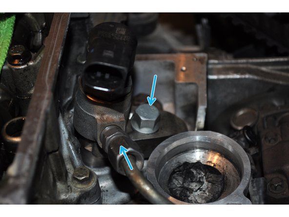
Utiliser une clé pour injecteur de 14, pour desserrer l'écrou de la conduite haute pression
-
Déposer la vis de la bride maintenant l'injecteur avec une douille de 13 mm
-
-
-
Retirer la vis et la bride
-
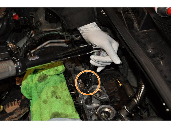
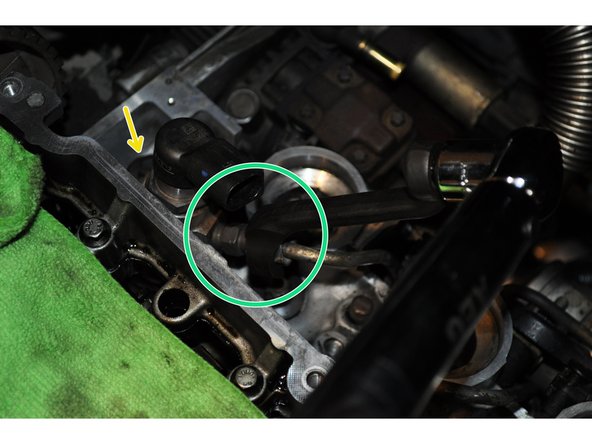
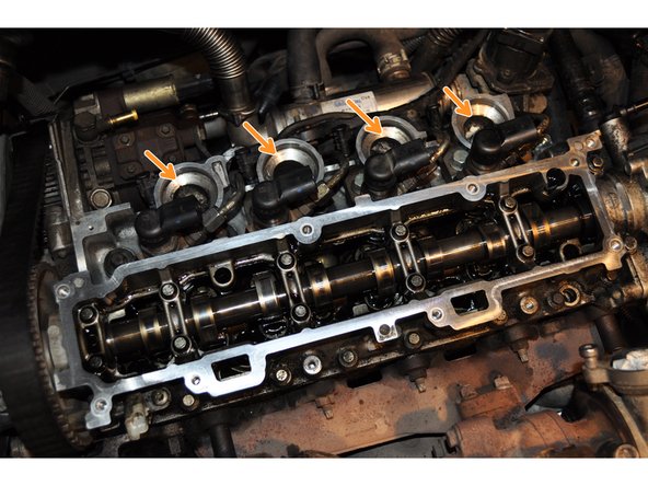
Débrancher le faisceau de conduite de gazole des 4 injecteurs
-
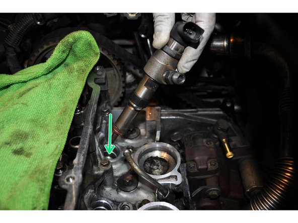
Retirer délicatement l'injecteur de son puit
-
-
-
Boucher les puits des injecteurs et continuer de nettoyer le dessus de la culasse du moteur
-
Organiser les injecteurs dans l'ordre exact de dépose. Il est primordiale de ne pas mélanger la combinaison injecteur/cylindre
-
Le joint d'étanchéité défectueux
-
-
-
Nettoyer les injecteurs sans toucher la pointe au risque de le boucher
-
Mettre en place le KIT MONTAGE JOINTS INJECTEUR CITROEN PEUGEOT 1.4 HDI
-
Le kit comprend la bague de centrage + le joint cuivre. La bague de centrage en plastique est généralement détruite à cause de la fuite qui remonte de long de l’injecteur.
-
Nettoyer avec précaution les puits des injecteurs
-
-
-
Mettre en place l'injecteur dans sa position initiale
-
Placer la bride et la vis s'assurant que l'alignement avec la conduite haute pression soit correct
-
Serrer la vis avec une clé dynamométrique Le couple de serrage de la bride d’injecteur est de 2.5 daN.m
-
-
-
Serrer l'écrou de la conduite haute pression avec une clé dynamométrique. Le couple de serrage des écrous haute pression est de 2.5 daN.m
-
Rebrancher le faisceau de conduite de gazole
-
-
-
Retirer l'ancien joint placé dans la partie cache culbuteurs puis nettoyer la rainure et placer le nouveau joint
-
Lubrifier légèrement les nouveaux joints torique et les mettre sur le cache culbuteur pour faciliter la repose
-
Nettoyer les portées de joint sans souiller l’intérieure de la culasse et des entrées d'air
-
-
-
Reposer le cache culbuteurs / collecteur d'air. Serrer les 8 + 2 vis
-
Reposer les tuyaux de gasoil
-
Reposer le carter supérieur de la courroie de distribution. Y fixer les différents éléments.
-
-
-
Reposer le support du filtre à gasoil
-
Puis le filtre à gasoil
-
Réamorcer le circuit de gasoil avec la pompe
-
Connecter les injecteurs
-
-
-
Reposer le résonateur d'air d'admission
-
Et le débitmètre de masse d'air
-
Rebrancher la batterie. Attendre 5 minutes que le calculateur s'initialise avant de mettre le contact
-
-
-
Vérifier que tout est correctement remonté, visé, câblé ...
-
Reposer la boite a air
-
Vérifier le bon fonctionnement
-


Annulation : je n'ai pas terminé ce tutoriel.
15 autres ont terminé cette réparation.

35 commentaires
Bonjour, pourquoi mes bagues de centrage en plastique n’ont pas le même diamètre intérieur que le corps de l’injecteur ? Les bagues ballent sur le corps des injecteurs, et la bague ne rentre pas dans le conduit ??? Pourtant le kit que j’ai acheté : M928A01, correspond bien à mon véhicule Citroen C2 moteur JM du 18/06/2004…
Nous sommes bien d’accord, la bague doit épouser le corps de l’injecteur sans jeu ?
Bonjour est-ce obligatoire d'avoir une clé spécial injecteur 14 ?
ghislain971 - Résolu à la publication Réponse
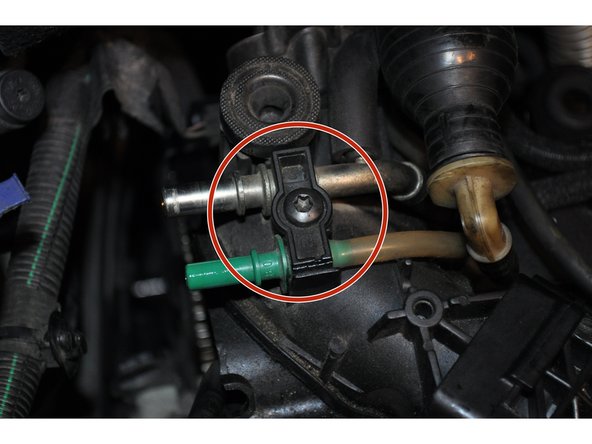
Bonjour et merci pour ce tuto. Petite question. Le tuyau qui va des injecteur au venturi (sorte de multiprise à gazol ou est branché aussi la poire) ce tuyau est diviser en 3.un grand tuyau, une vanne anti retour marquée d'une flèche et un autre petit morceau de tuyau. Leje l'ai remontée à l'envers car j'ai suivi le sens de circulation du gazol, après tout, ça me paraissait logique avec la flèche. Et pourtant la flèche dois être mise en direction du venturi et non des injecteurs. Alors est-ce vraiment une vanne anti retour ? J'ai pu démarré et faire tourner la voiture mais j'ai l'erreur systeme antipollution. Demain je vais remettre ça comme s'était mais savez pourquoi la flèche donne la direction opposé du carburant ?
Merci pour ce tuto très bien fait !
Je suis arrivé au bout , cela m’aura pris une semaine et demi, en partie à cause du nettoyage…mais étant totalement novice en mécanique j’ai pris mon temps.
Le redémarrage m’a pris deux jours, recharge de la batterie, demarrage au chargeur-démarreur, gros réamorçage de la pompe à gazoil et start pilote ds la conduite d’air elle à finit par redémarrer.
Le voyant moteur est resté allumé pdt deux jours (+ 3 bips sonores) puis plus rien…
Le moteur fonctionne nickel rien à signaler.
Merci encore.