Introduction

This tutorial is made on Volkswagen Passat B6 - 1.9 TDI 105

  1. Lift the vehicle Remove the right front wheel Remove the right front wheel
    • Lift the vehicle

    • Remove the right front wheel

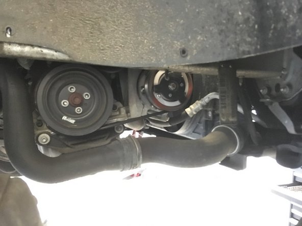
  2. Unscrew the 11 T25 and T40 screws Remove the under-engine plate
    • Unscrew the 11 T25 and T40 screws

    • Remove the under-engine plate

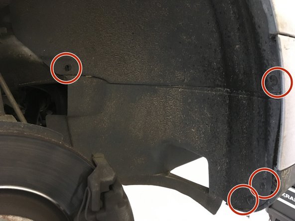
  3. Unscrew the 4 T25 screws Remove the wheel arch
    • Unscrew the 4 T25 screws

    • Remove the wheel arch

  4. Remove the engine cover by pulling upwards Remove the engine cover by pulling upwards
    • Remove the engine cover by pulling upwards

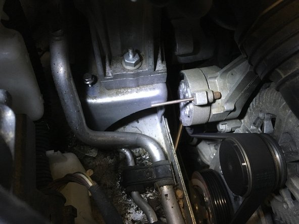
  5. Using an 18 mm flat wrench, loosen the tensioner roller. Insert a pin to block the tensioner roller in order to remove the belt Insert a pin to block the tensioner roller in order to remove the belt
    • Using an 18 mm flat wrench, loosen the tensioner roller.

    • Insert a pin to block the tensioner roller in order to remove the belt

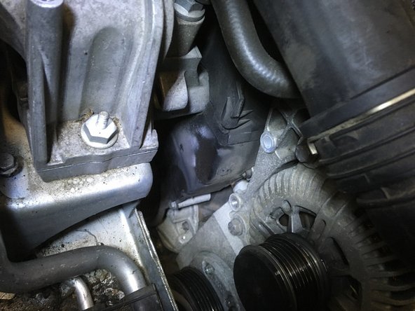
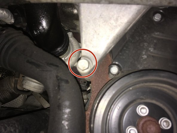
  6. Unscrew the two 16 mm screws Remove the tensioner roller
    • Unscrew the two 16 mm screws

    • Remove the tensioner roller

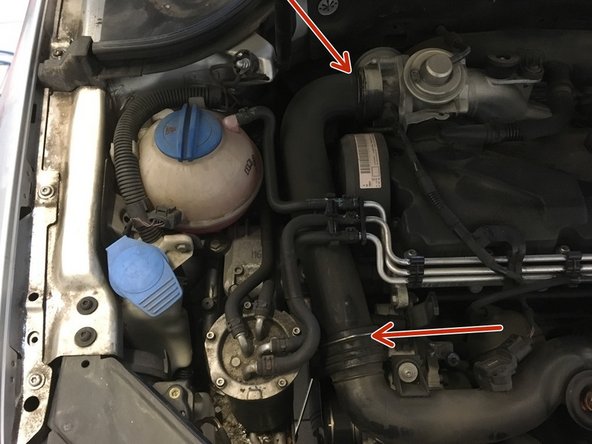
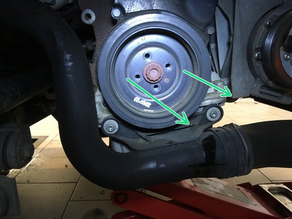
  7. Remove the air hose by removing the two clips Remove the air hose by removing the two clips
    • Remove the air hose by removing the two clips

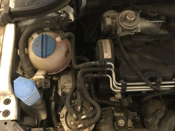
  8. Unscrew the two T25 screws and tilt the jar to access the engine mount Unscrew the two T25 screws and tilt the jar to access the engine mount
    • Unscrew the two T25 screws and tilt the jar to access the engine mount

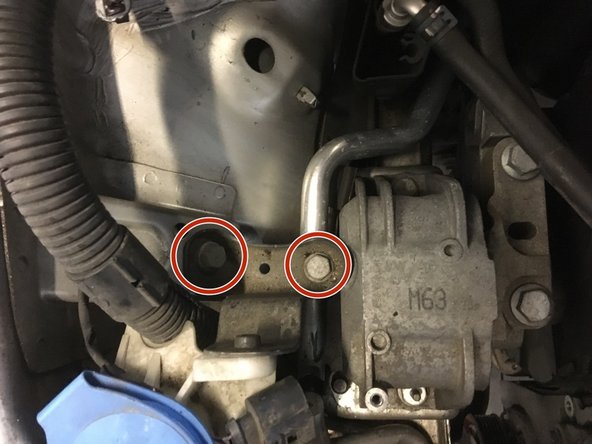
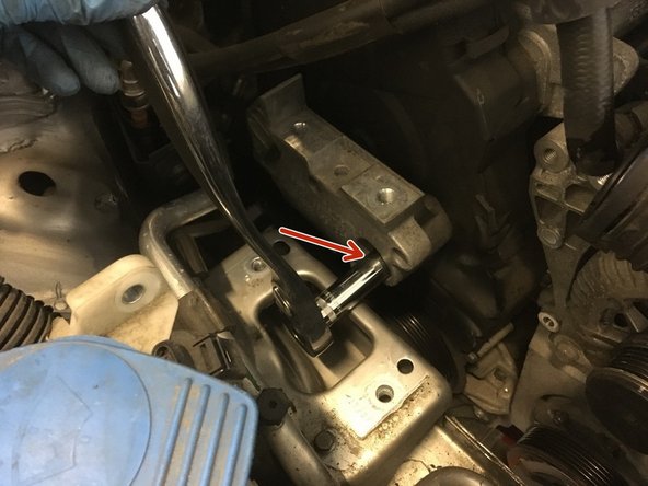
  9. Unscrew the two 16 screws to remove the tab Unscrew the two 16 screws to remove the tab
    • Unscrew the two 16 screws to remove the tab

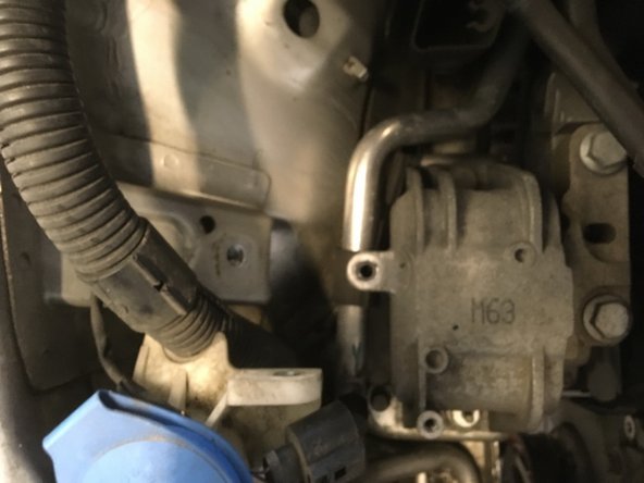
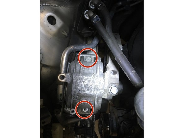
  10. Place a jack under the engine and lift it slightly to be able to remove the engine mount.
    • Place a jack under the engine and lift it slightly to be able to remove the engine mount.

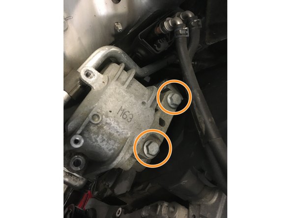
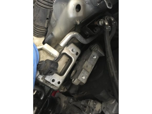
  11. Unscrew the two 16 mm screws Unscrew the two 18 mm screws Remove the engine mount
    • Unscrew the two 16 mm screws

    • Unscrew the two 18 mm screws

    • Remove the engine mount

  12. Remove the 3 screws of 16 Remove the 3 screws of 16 Remove the 3 screws of 16
    • Remove the 3 screws of 16

  13. Remove the distribution cover by unclipping the three clips Remove the engine mount Remove the engine mount
    • Remove the distribution cover by unclipping the three clips

    • Remove the engine mount

  14. Unscrew the 4 xzn screws Remove the damper pulley Remove the damper pulley
    • Unscrew the 4 xzn screws

    • Remove the damper pulley

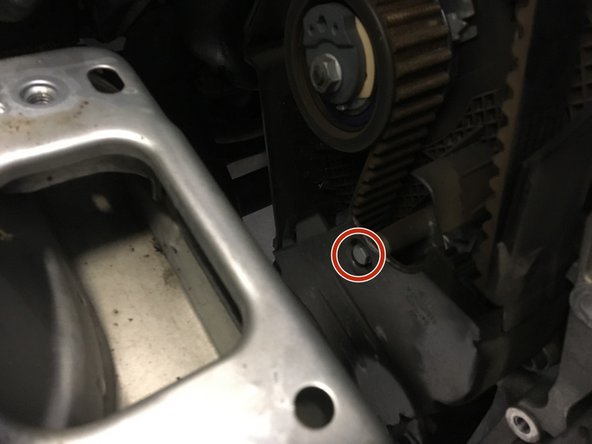
  15. Unscrew the 5 screws of 10 Remove the distribution cover Remove the distribution cover
    • Unscrew the 5 screws of 10

    • Remove the distribution cover

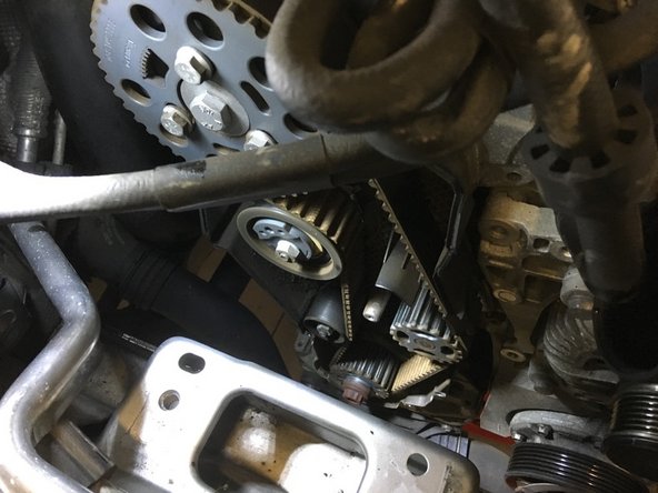
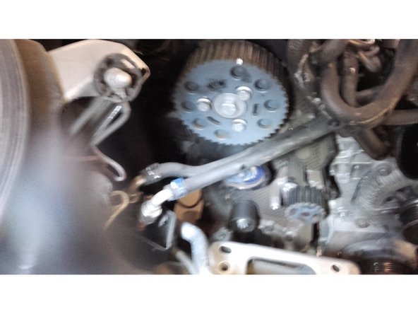
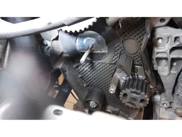
  16. Turn the motor using the E24 socket until the markings align Insert the timing pins to lock the camshaft and crankshaft Insert the timing pins to lock the camshaft and crankshaft
    • Turn the motor using the E24 socket until the markings align

    • Insert the timing pins to lock the camshaft and crankshaft

  17. Loosen the 15 screw and relax the tensioner roller Identify the belt routing diagram and then remove the Identify the belt routing diagram and then remove the
    • Loosen the 15 screw and relax the tensioner roller

    • Identify the belt routing diagram and then remove the

  18. Remove the tensioner roller
    • Remove the tensioner roller

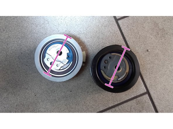
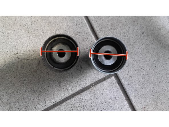
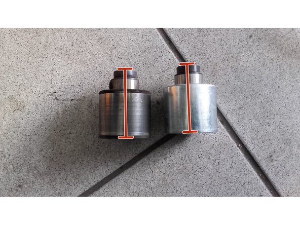
  19. Check that the new roller matches the old one
    • Check that the new roller matches the old one

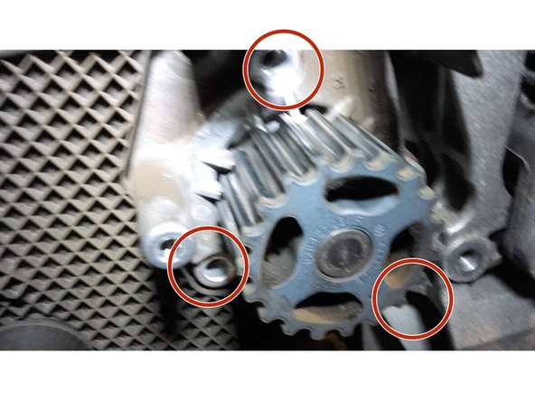
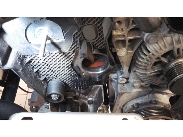
  20. Unscrew the 3 screws of 10 Remove the water pump If you have not previously drained your cooling circuit, it will flow out when you remove the water pump. Therefore, place a collection tray under it.
    • Unscrew the 3 screws of 10

    • Remove the water pump

    • If you have not previously drained your cooling circuit, it will flow out when you remove the water pump. Therefore, place a collection tray under it.

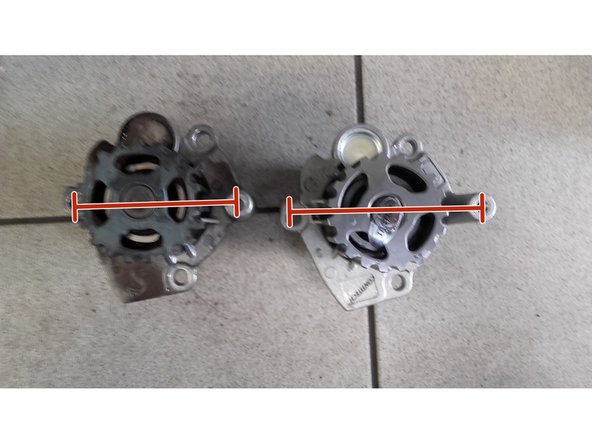
  21. Check that the new water pump matches the old one Check that the new water pump matches the old one
    • Check that the new water pump matches the old one

  22. Reassemble the new water pump
    • Reassemble the new water pump

    • Aim the 3 screws of 10

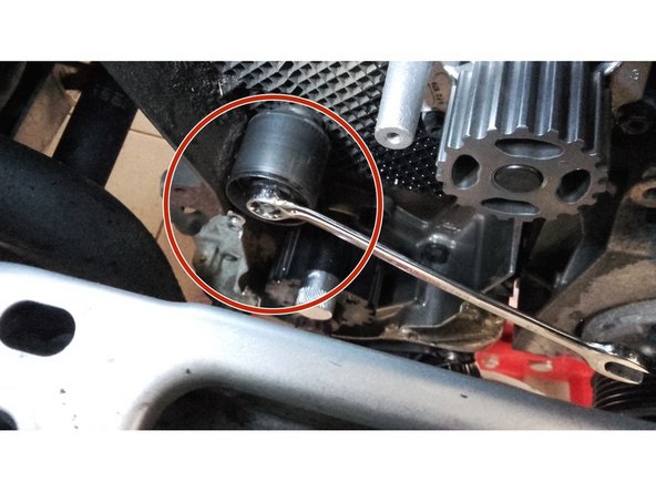
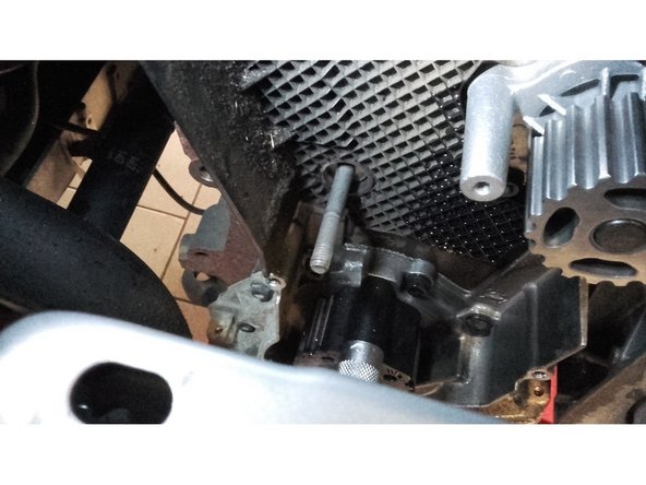
  23. Unscrew the 15 screw and remove the roller. Unscrew the 15 screw and remove the roller.
    • Unscrew the 15 screw and remove the roller.

  24. Check that the two rollers match Check that the two rollers match
    • Check that the two rollers match

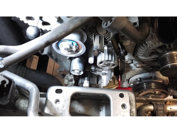
  25. Install the new roller and tighten the 15 screw to the manufacturer's torque.
    • Install the new roller and tighten the 15 screw to the manufacturer's torque.

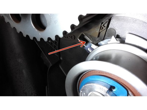
  26. Install the new tensioner roller, taking care to position the tab in its housing
    • Install the new tensioner roller, taking care to position the tab in its housing

  27. Install the new belt Install the new belt
    • Install the new belt

  28. Using the 6 mm Allen key, tension the belt. Align the mark to achieve the correct tension
    • Using the 6 mm Allen key, tension the belt.

    • Align the mark to achieve the correct tension

    • Tighten the 15 nut to the manufacturer's torque.

  29. Make two turns of the motor using the ratchet and the E24 socket Check that once the two turns have been completed the pins go back into their housing
    • Make two turns of the motor using the ratchet and the E24 socket

    • Check that once the two turns have been completed the pins go back into their housing

    • Remove the pins

    • Reassemble everything in the reverse order of disassembly.

  30. Pour the coolant into the jar
    • Pour the coolant into the jar

    • Start the engine

    • the cooling circuit purges itself on this vehicle model

    • Let the engine run until the cooling fan comes on several times

    • Stop the engine, and check the level after the engine has cooled completely.

Finish Line

4 other people completed this guide.

dlychar

Member since: 10/09/2017

10,089 Reputation

70 Guides authored

13 Comments

Good morning,

in step 16 you ask to put the marks correctly, but in the photo we see that the mark is in TDC and is not aligned with the timing system...

is this a mistake or not?

THANKS

jmgerdolle - Reply

Hello, the BTR key must be turned counterclockwise to be able to tighten the belt, and align the arrow with the mark, that's all.

alis.rome - Reply

Hello, very good tutorial. However, is it normal that the arrow indicating the direction of rotation indicates an anti-clockwise direction, except that the tension on this model is done in the clockwise direction, indicated by an arrow on the tensioner roller. Thanks in advance

joseph martin - Reply

Good morning

Thank you for your help!

BUT I DON'T THINK IT'S ON AN AUDI A4 TYPE B6

No ??

jean jacques bourrier - Reply

How to make two engine turns while the pins are in place.

Or the order is wrong in the operations.

Vincent Gros - Reply

Add Comment

View Statistics:

Past 24 Hours: 6

Past 7 Days: 20

Past 30 Days: 137

All Time: 27,482