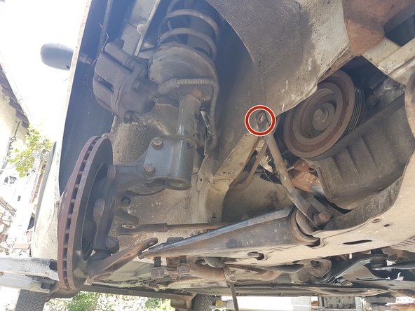
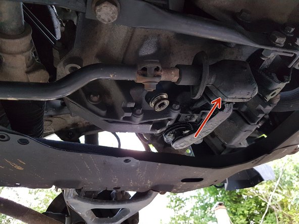
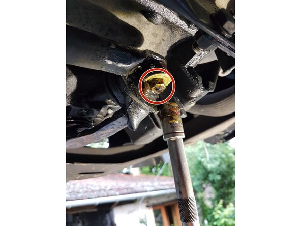
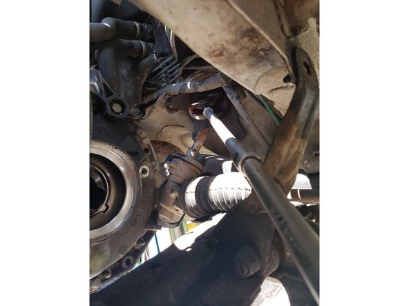
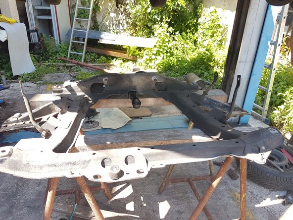
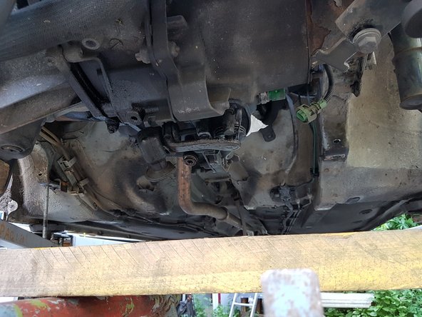
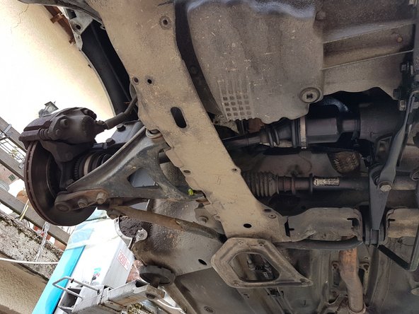
Introduction
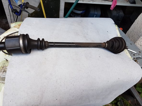
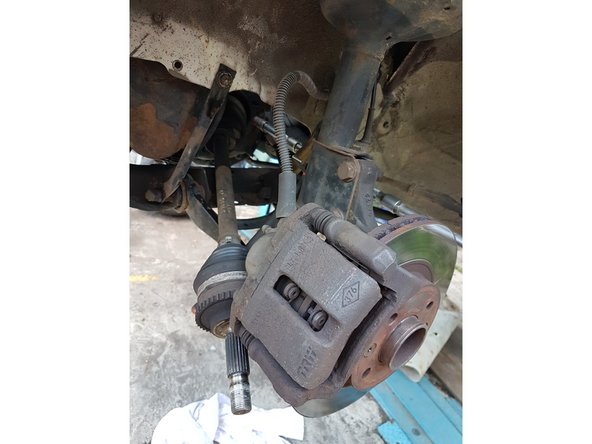
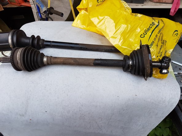
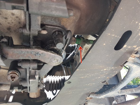
Ce tutoriel est réalisé sur une Renault Clio 2 1.5dci
-
-
Avant de commencer cette opération:
-
- vous DEVEZ avoir votre RTA
-
- Respecter les couples de serrage
-
- travailler en sécurité (gant et lunette)
-
- Prévoyez une 2ème personne, pour la dépose du berceau et de la boite de vitesse
-
N'oubliez pas, la précipitation est mauvaise conseillère !!
-
-
-
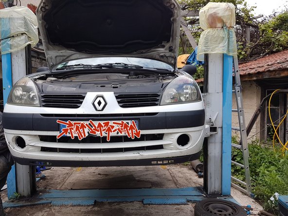
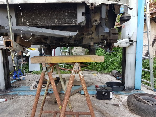
Mettre la voiture sous chandelles ou sur pont.
-
Dévisser les 4 écrous de chaque roues avant et déposer les roues.
-
-
-
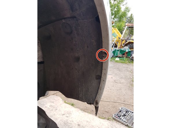
Enlever les deux écrous de 13 sur le dessus du bouclier.
-
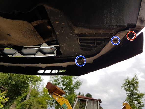
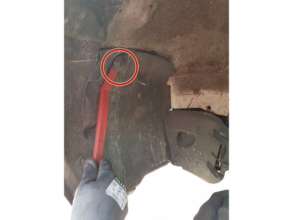
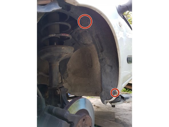
Dévisser les vis qui tiennent le bouclier par le bas (elles sont toutes visibles facilement, vous pouvez en avoir plus que celles de la photo)
-
En bleues, ce sont des attaches plastiques qu'il faut retirer (ils tiennent une partie du garde boue en plastique et vous génera quand vous tirerez le bouclier)
-
Si vous avez des antibrouillards, enlevez les.
-
-
-
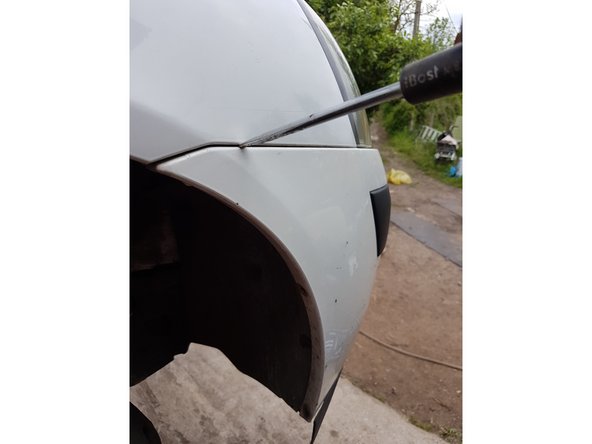
Dégrafer le pare choc à l'aide d'un tournevis ou d'une cale en plastique si vous ne voulez pas trop l'abimer.
-
N'oubliez pas de faire la même chose de l'autre coté !
-
Ensuite, il suffit de tirer le pare choc vers vous tout en vérifiant que vous n'avez pas oubliez une vis ou une accroche plastique (en carré rouge)
-
NB: pensez à déconnecter les antibrouillards si vous en avez.
-
-
-
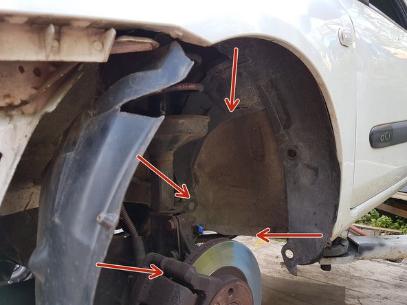
Enlever les vis et les inserts plastiques qui tiennent le garde boues.
-
Ils sont tous visibles et accessibles
-
-
-
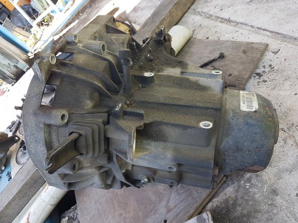
Le but est de pouvoir dégager la boite de vitesse (carré bleu), dans laquelle se trouve le disque d'embrayage à changer.
-
Pour cela, il faudra enlever le berceau (flèche rouge).
-
Et aussi enlever :
-
en rouge: le cardan
-
en bleu: la crémaillère de direction
-
en jaune: les freins
-
en vert: le pivot sur triangle
-
Il faudra faire ces manipulations de l'autre coté également.
-
-
-
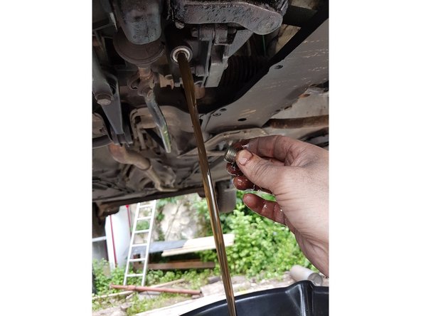
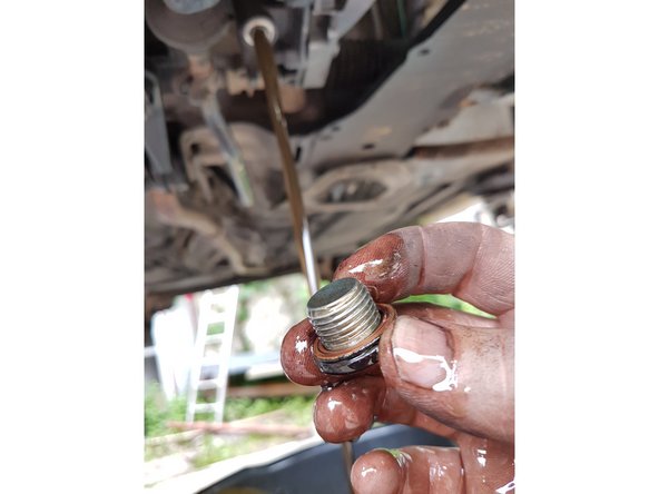
On commence par vidanger la boite.
-
On récupère le bouchon et on changera le joint quand on le remontera.
-
-
-
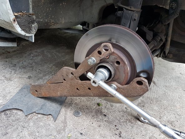
Comme il va falloir enlever le cardan, on démonte l'écrou du moyeu.
-
Bloqué le moyeu avec un appareil (fait maison ou non), puis dévisser avec une rallonge (douille de 32).
-
Faite la meme chose de l'autre coté.
-
-
-
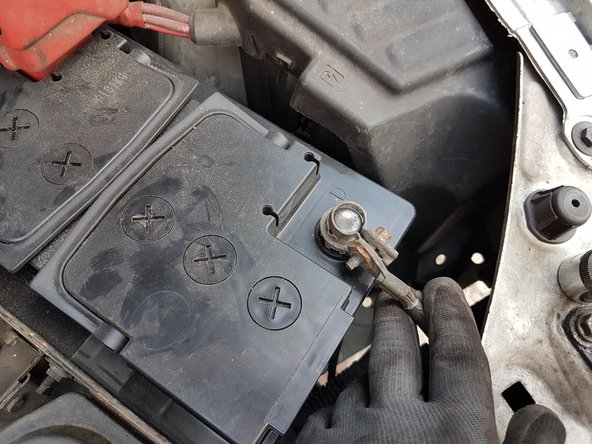
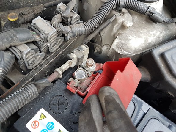
On débranche la batterie (douille de 8 et 10)
-
Et on dévisse le support de batterie qui se trouve en bas à droite de la batterie (douille de 13 avec rallonge)
-
-
-
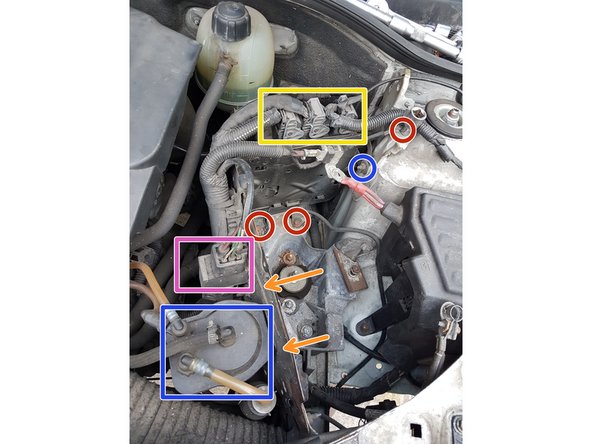
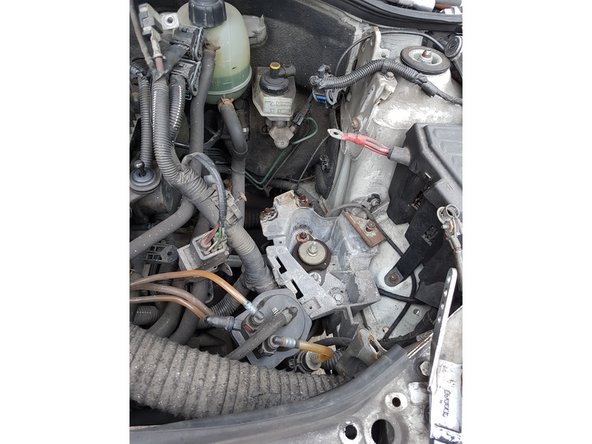
Démonter le support batterie n'est pas difficile, il n'y a que quelques vis à enlever.
-
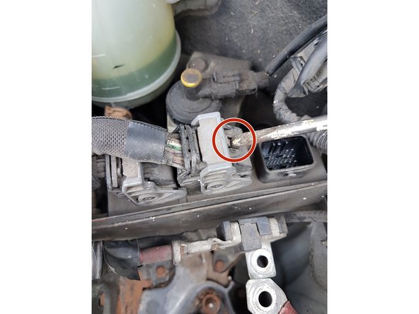
Jaune: le calculateur a déconnecter avec un tournevis (cf photo)
-
rouge : les vis du support de batterie (attention, il y en a une dessous !)
-
en orange: 2 vis torx a enlever
-
en bleu: le filtre à gazole (il suffit de l'amener vers le haut une fois la vis enlever) Note: Le laisser connecter.
-
En rose: petit boitier (je ne sais pas ce que c'est), qui s'enleve une fois la vis torx déposé.
-
-
-
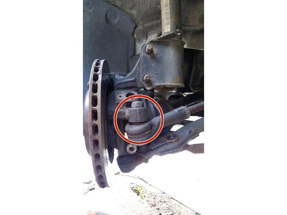
Déserrer l'écrou de rotule de direction
-
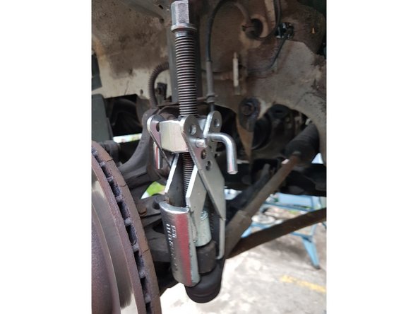
Avec un arrache rotule, déloger la rotule (en s'aidant de l'écrou comme appuye, ne prenez pas la vis directement car vous risquerez d'abimer le pas de vis).
-
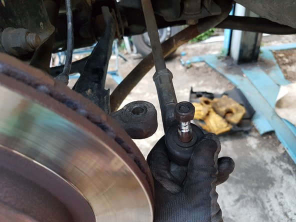
Une fois la rotule déloger, pour pouvoir dévisser l'écrou complètement, il faut que vous fassiez pression sur la rotule par dessous.
-
-
-
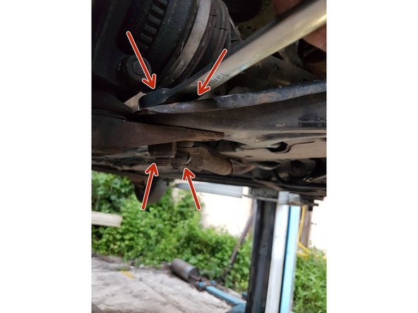
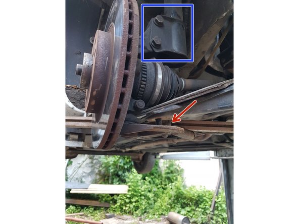
Dévisser les écrous de la rotule (en prenant soins d'en laisser une pas totalement dévissée)
-
Ensuite écarter la rotule avec le triangle de direction.
-
Remarque: le pivot est toujours maintenu par le bras de suspension que nous n'avons pas enlevé (carré bleu)
-
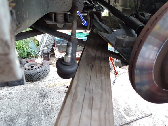
Puis, faite levier avec une planche ou une barre en fer en passant par dessus la barre stabilisatrice, et par dessous le triangle de direction.
-
En appuyant légerement, vous pourrez finir de dévisser l'écrou completement, et déloger la rotule du triangle.
-
Faites attention que le soufflet de cardan ou le caoutchouc de la rotule ne s'abime sur les autres éléments.
-
-
-
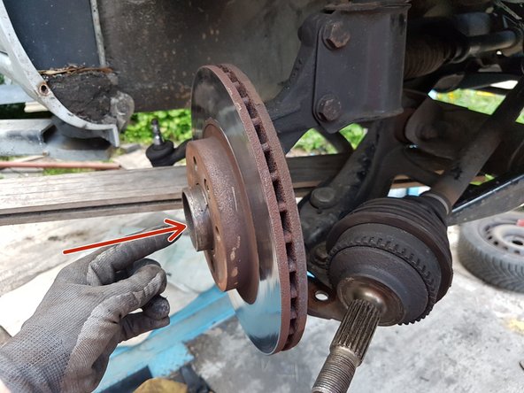
Pousser le cardan du moyeu, en tournant le pivot sur sa droite à fond pour pouvoir l'enlever.
-
Puis simplement tirer le cardan à soi.
-
Certains peuvent avoir une vis ou un circlips à enlever coté moteur.
-
-
-
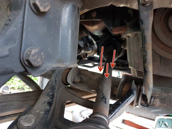
En premier, déloger le cardan du moyeu.
-
Dévisser les 3 vis qui tiennent le cardan coté boite.
-
Puis tirer le cardan à vous.
-
Protéger le cardan des saletés en lui mettant un sac au niveau du tripod.
-
-
-
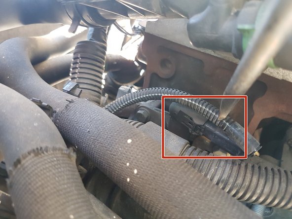
On en profite pour débrancher le capteur de marche arrière
-
il suffit d'appuyer de chaque coté et de tirer vers soi.
-
-
-
De chaque coté de la voiture, enlever les écrous des montants carrosserie/berceau.
-
-
-
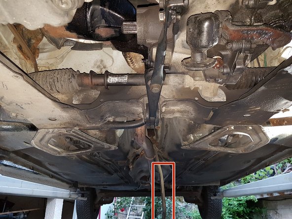
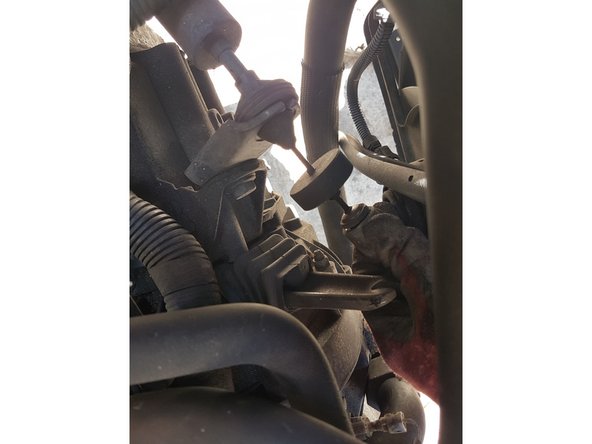
Sous la voiture, enlever le caoutchouc de protection pour accéder à la vis qui tient la commande de vitesse.
-
Dévisser l'écrou.
-
Une fois dévisser (dans le carrée rouge), attacher la commande sur la ligne d'échappement pour ne pas qu'elle vous embete en pendant.
-
-
-
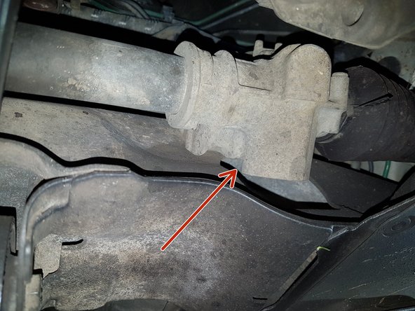
La crémaillère n'est tenu que par deux écrou et la direction.
-
Les écrous restent assez accessible
-
-
-
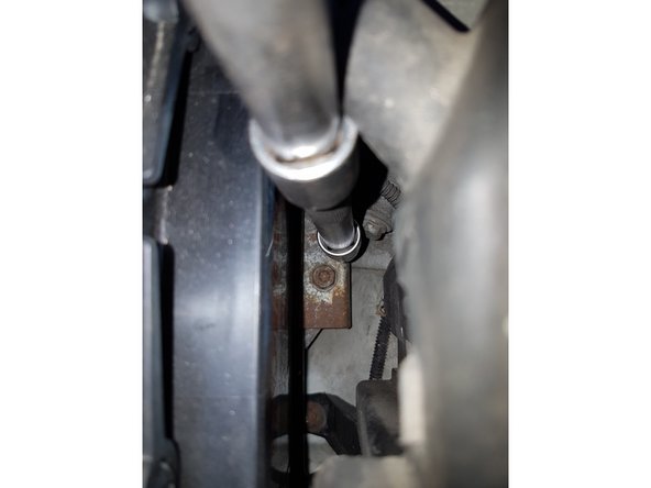
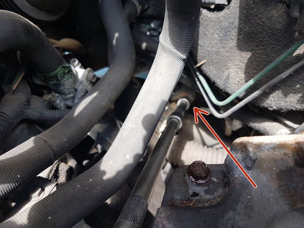
En regardant par le dessus, on peut voir l'écrou qui tient la direction.
-
Si l'écrou n'est pas vraiment accessible, il suffit de tourner le volant.
-
Une fois dévissé et l'écrou enlevé, je me suis servi d'une rallonge carré que j'ai mise dans la gorge, puis j'ai tourné mon carré de facon à écarter un peu la gorge pour que la crémaillère puisse s'enlever de la barre de direction.
-
Quand vous l'avez déboité, il suffit de faire sortir la crémaillère par la droite ou la gauche, tout dépend de la place que vous avez.
-
-
-
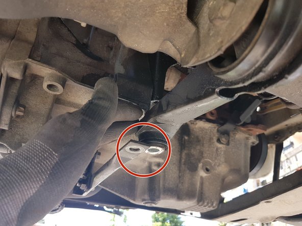
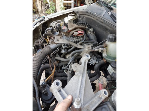
Dévisser la vis du support moteur bas.
-
ATTENTION: Ne pas dévisser l'autre vis !
-
Le support a du jeu axial, ce qui nous permettra d'enlever le berceau en le déplacant à gauche ou à droite.
-
-
-
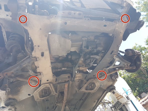
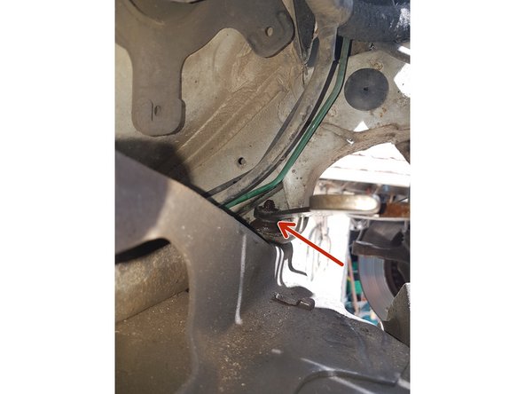
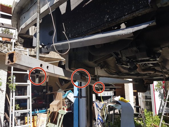
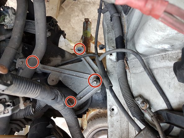
Dévisser les 4 vis des triangles berceau/chassis.
-
ATTENTION: ne pas les dévisser à fond pour le moment !
-
Dévisser ensuite les 4 vis qui tiennent le berceau.
-
ATTENTION: ne pas dévisser les vis à fond !
-
Il y a de forte chance pour que les stop-écrou se casse lorsque vous les déserrerer (ils sont tenu par un petit bout de metal vers la fleche rouge).
-
-
-
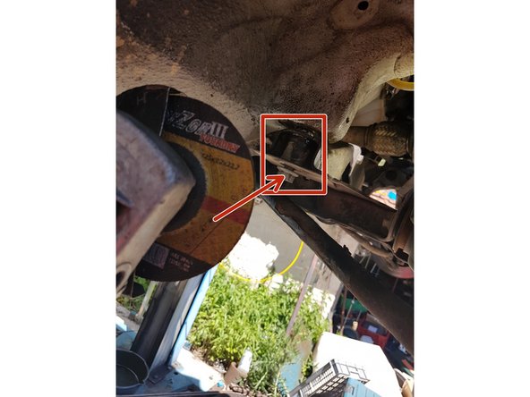
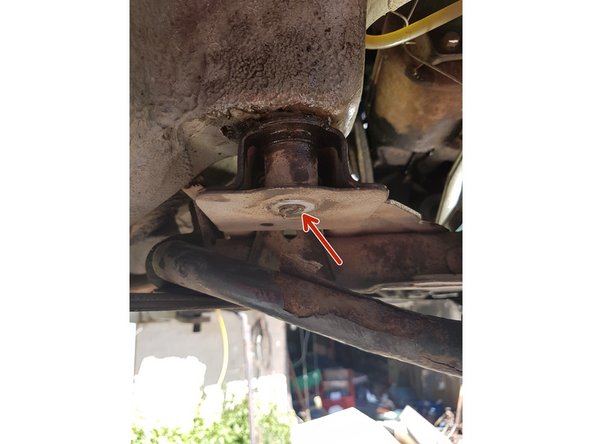
deux solutions pour enlever les écrous :
-
Réussir à passer une clé pour bloquer l'écrou qui est dans la carrosserie
-
ATTENTION: Pour cela enlever la vis métallique qui servait de blocage et qui a cassé car vous ne pourrez pas mettre votre clé correctement sur l'écrou !
-
Ou alors disquer la vis ... !
-
-
-
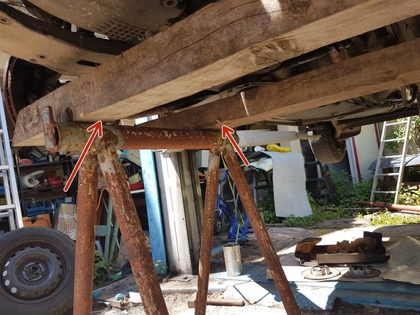
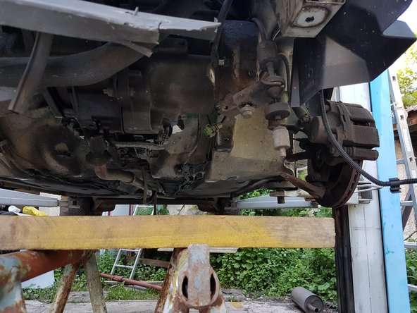
Mettre des cales sous le berceau ou des crics.
-
Une fois que vous avez mis les cales, vous pouvez dévisser completement toutes les vis que nous avions laissé par sécurité.
-
Ensuite faite descendre le berceau en faisant attention de bien dégager le support moteur bas et de ne pas accrocher d'autres parties.
-
Les deux vis berceau/chassis peuvent etre dur à enlever à cause de la rouille et du faite qu'elles soient coniques. Il faudra tapoter avec un marteau pour les enlever.
-
-
-
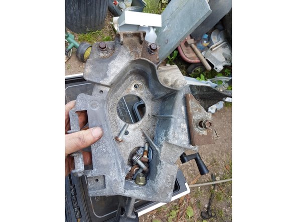
Le berceau déposé.
-
En rouge les vis principales du berceau (il y en a 4 que l'on ne voit pas derrière)
-
En bleu le support moteur qu'il faut faire attention lorsqu'on enleve le berceau.
-
-
-
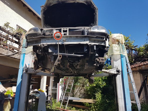
Pour ne pas que le moteur bascule lorsque nous enleverons la boite de vitesse, il faut mettre un support sous le moteur.
-
Notre support maison est une barre avec une tige à chaque extrémité, l'une allant dans le trou du boulon du berceau, et l'autre coté dans un trou présent sur le devant de la voiture.
-
En milieu, support métallique pour tenir le moteur.
-
-
-
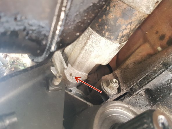
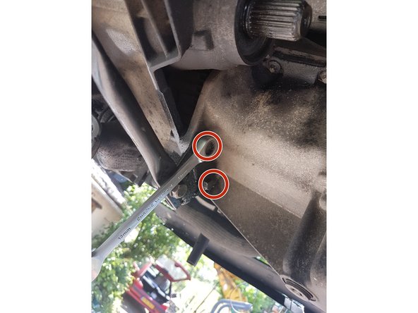
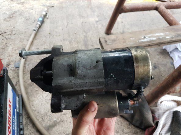
Localiser le démarreur. Il est derrière le moteur lorsqu'on regarde par dessous, entre le moteur et la crémaillère de direction.
-
Enlever les deux vis qui tiennent le démarreur.
-
Dégager le démarreur à l'aide d'un tournevis.
-
Si vous n'y arrivez pas, attendez d'enlever la boite de vitesse, le démarreur s’enlèvera de lui même.
-
-
-
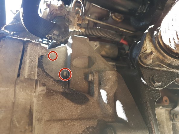
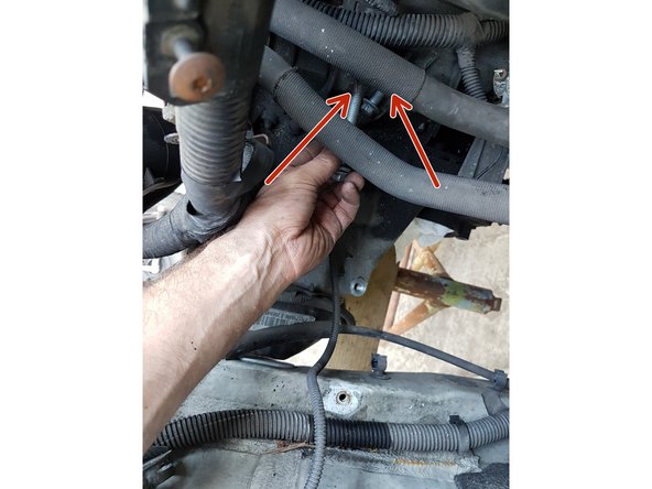
Dérrière le démarreur, enlever les deux vis qui tiennent le support de masse sur la boite de vitesse.
-
-
-
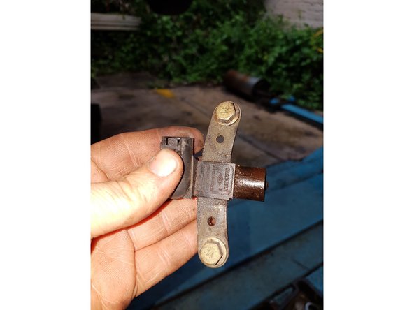
Il se situe sur le haut de la boite de vitesse.
-
Déconnecté le avec un tournevis.
-
Dévisser les 2 vis qui le tient.
-
Déposer le capteur.
-
-
-
Déconnecter le cable d'embrayage. ATTENTION: La photo ne veut pas se mettre dans le bon sens ! La fleche rouge indique où était le cable d'embrayage (rond rouge).
-
Sur le support du cable d'embrayage, enlever la vis.
-
On en profite pour enlever le cable de masse également.
-
-
-
Caler la boite de vitesse de facon à pouvoir ensuite enlever le support de boite.
-
Caler là avec des morceaux de bois ou des crics.
-
Attention: Il ne faut pas trop surélever la boite car cela risquera de jouer sur le moteur et donc sur les poulies coté alternateur !
-
-
-
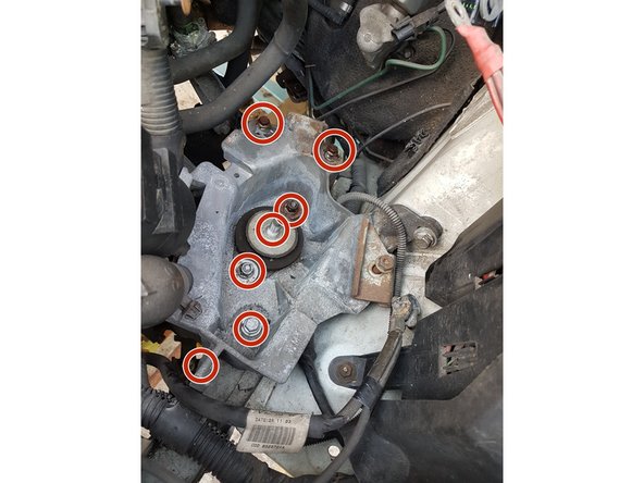
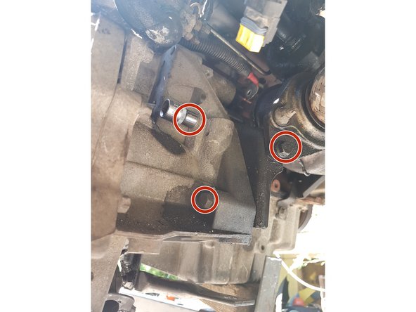
Dévisser les vis du support de boite.
-
Il y a également une vis en dessous du support.
-
ATTENTION: Ne pas dévisser complétement les 3 vis du milieu si vous n'avez pas encore mis de support sous la boite !!
-
Si vous avez bien mis le support de boite, alors vous pouvez dévisser puis enlever le support de boite.
-
-
-
Sous le support de boite, il y a un autre support sur la boite qui sert pour mettre des cables.
-
Dévisser le tout simplement pour l'enlever.
-
-
-
Pour déboiter la boite, commencer par dévisser les vis de tour de boite.
-
Au fur et à mesure que vous dévisserer la boite, vous commencerez à voir le volant moteur.
-
-
-
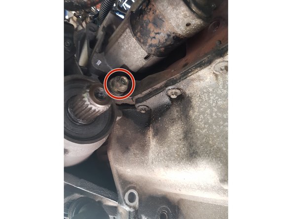
Vous avez également 2 vis à enlever qui se trouve sur le haut (flèche rouge) du tour de boite.
-
Dévissé l'écrou qui se trouve sous le démarreur, qui sert de guide sur la partie arrière de la boite.
-
Il y en a également un sur le devant de la boite.
-
Grace à ses deux guides, vous pouvez enlever toutes les vis de tour de boite, les guides retiennent la boite.
-
-
-
Pour enlever la boite de vitesse , il faut la décaler vers la droite, tout en la baissant pour quelle puisse passer sous la carrosserie.
-
Il faut la décaler jusqu'à ce qu'elle puisse sortir des guides.
-
ATTENTION: Il faut jouer avec le support moteur pour pouvoir descendre la boite tout en faisant attention à ce que les poulies moteur ne touchent pas la carrosserie !
-
Avec notre outil, nous pouvons basser ou lever le moteur pour que les poulies ne touche pas la carrosserie.
-
-
-
Enlever la boite en faisant attention à ce que des vis ou des durites ne bloquent pas sa progression.
-
-
-
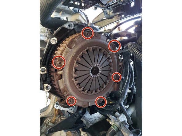
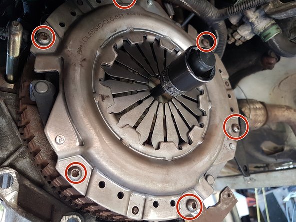
Noter l'emplacement du mécanisme avant de défaire les vis.
-
Dévisser les 6 vis du mécanisme.
-
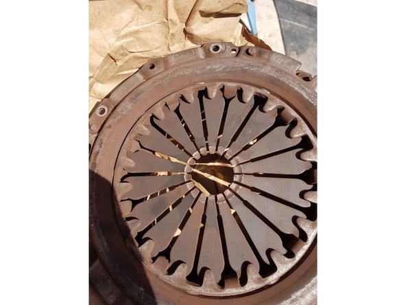
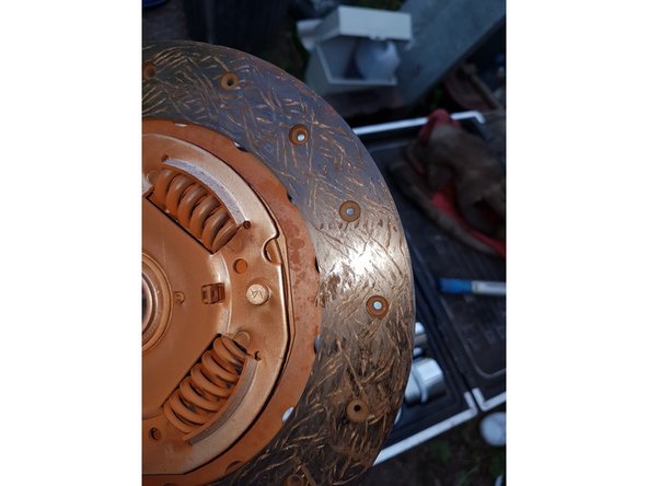
Cela laissera apparaitre l'embrayage que vous pourrez déposer.
-
-
-
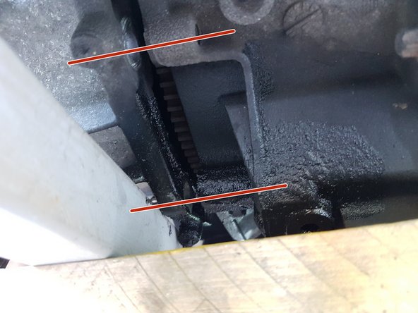
Ici on voit mieux les guides qui permettent de glisser la boite de vitesse sur le moteur
-
Garder les en mémoire pour le remontage.
-
-
-
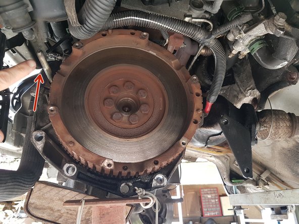
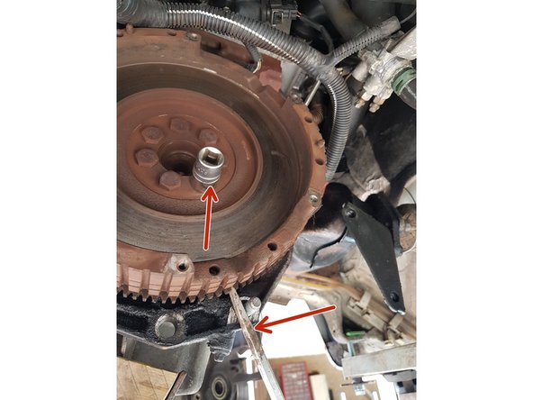
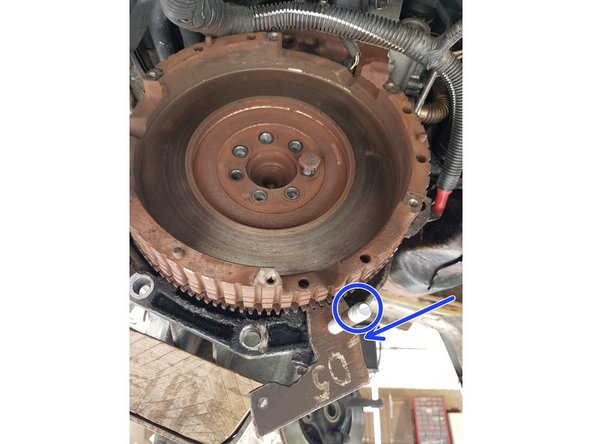
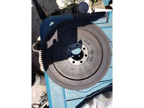
Déviser les 7 vis qui retiennent le volant moteur. Bloquer le volant moteur pour pouvoir les enlever.
-
- Soit avec un tournevis si vous y arriver
-
- Soit en fabricant un petit outil (on pourra s'aider du guide de boite)
-
Déposer le volant moteur simplement en tirant dessus.
-
-
-
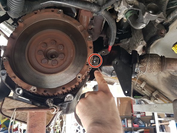
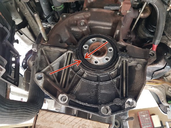
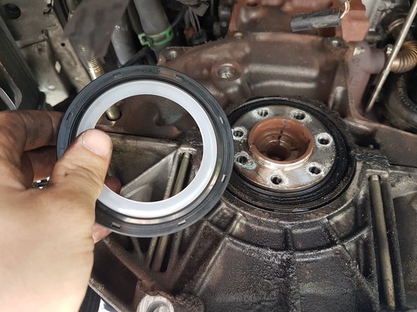
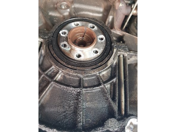
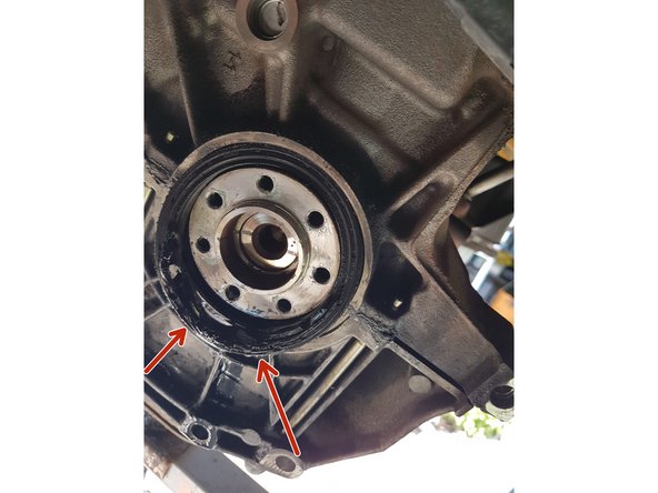
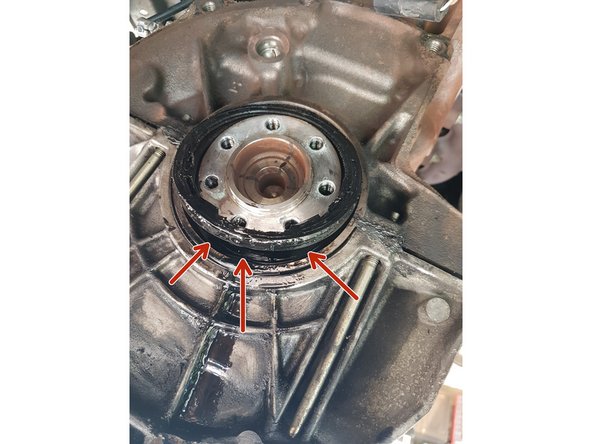
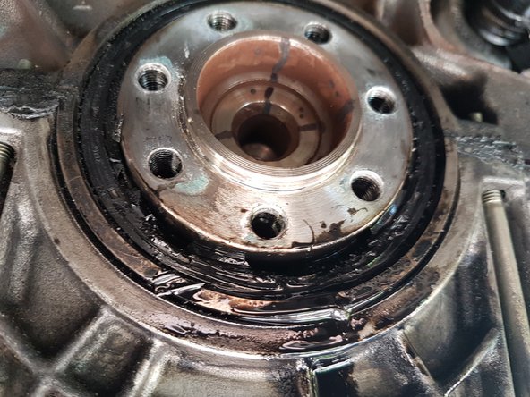
Une fois le volant moteur déposé, on voit le joint SPI apparaitre.
-
On en profite pour vérifier que celui qui est fournit dans le kit soit bien le même.
-
On remarquera que j'avais une petite fuite à ce niveau.
-
-
-
Pour enlever le joint, il faut s'aider d'un petit tournevis plat pour essayer de l'enlever.
-
Vous pouvez déchirer ou découper le joint SPI mais attention à ne pas abimer les autres pièces !
-
-
-
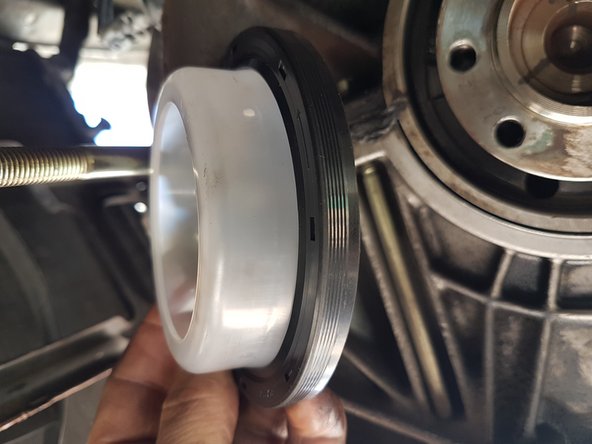
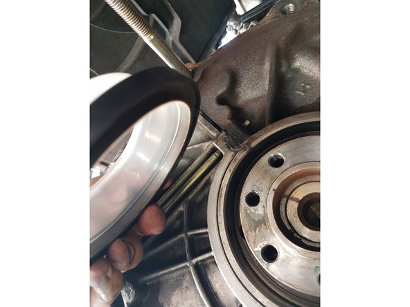
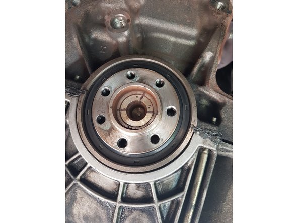
En s'aidant du guide fournit, mettre le nouveau joint SPI à la place de l'ancien.
-
Tapoter un peu sur le joint pour l'enfoncer uniformément jusqu'à la butée.
-
-
-
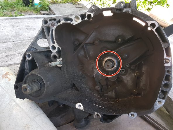
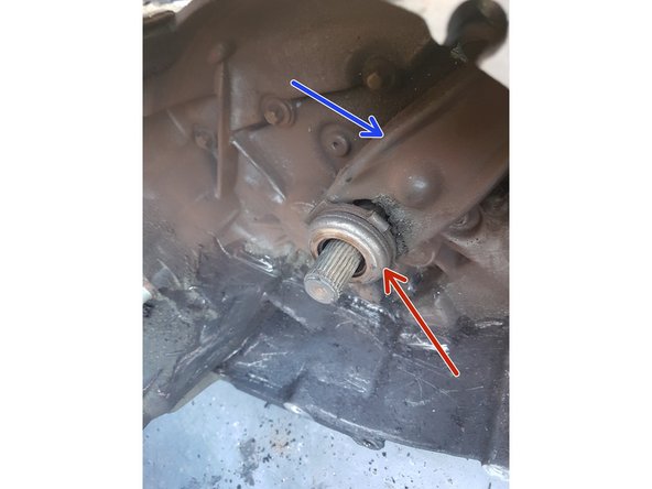
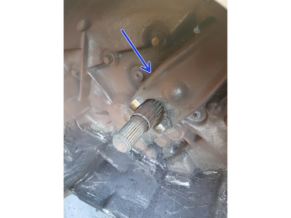
Coté boite de vitesse, vous verrez apparaitre en plein milieu la butée d'embrayage ainsi que la fourchette.
-
Enlever la butée, en rouge (il faudra mettre la nouvelle)
-
Enlever la fourchette, en bleu, que l'on remettra par la suite.
-
-
-
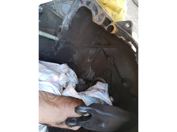
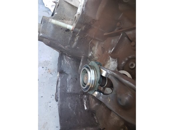
Nettoyer l'axe pour préparer la mise en place de la nouvelle butée.
-
Graisser l'axe cannelé avec la graisse adéquate (voir sur la RTA).
-
Mettre en place la nouvelle butée
-
-
-
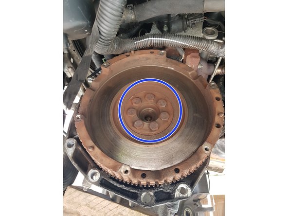
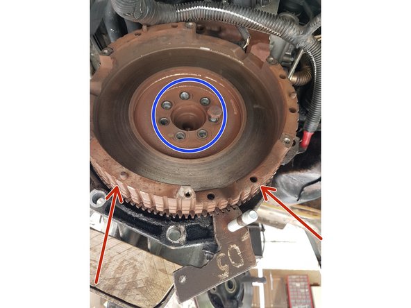
A l'aide de l'outil utilisé pour enlever le volant moteur, nous le remettons.
-
Serrer les 7 vis au couple prescrit dans la RTA.
-
- En rouge, le volant moteur.
-
- En bleu, les 7 vis qui tiennent le volant moteur.
-
Serrer les vis au couple de serrage de la RTA.
-
-
-
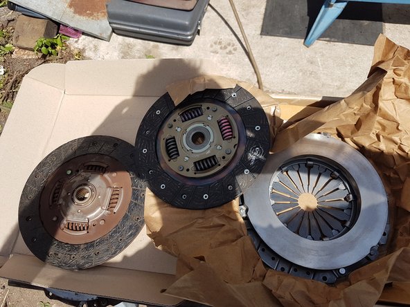
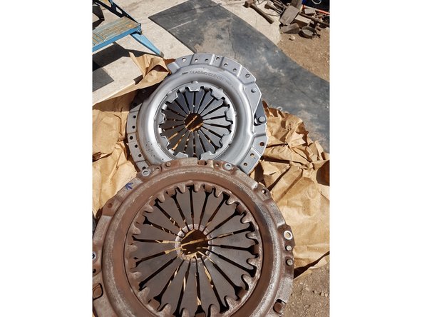
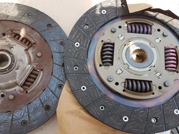
Prendre le nouveau disque et le mettre dans le nouveau mécanisme d'embrayage.
-
Puis mettre l'ensemble sur le volant moteur précédemment remonté.
-
Vissez les 6 vis pour soutenir l'ensemble.
-
Centrer le disque d'embrayage avec un centreur.
-
Si le disque n'est pas trop centré, ce n'est pas trop grave, le soucis est que cela sera plus dure de remboiter la BV sur le moteur.
-
Visser completement les vis au couple prescrit une fois que le centrage est à peu près correct.
-
-
-
Pour remonter, il faut faire les opérations inverses.
-
Pêle mêle les éléments principaux à remonter, donné à titre indicatif seulement :
-
- la boite de vitesse
-
- le capteur de volant moteur
-
- l'alternateur
-
ATTENTION: lorsque vous remettez la BV, faites toujours attention que les poulies coté droit ne touche pas la carrosserie !
-
REMARQUE: n'oubliez pas de faire passer les cables du bon coté avant de remonter l'ensemble (cable de masse notamment).
-
-
-
Continuer par remettre:
-
- le cable d'embrayage
-
- le cardan de direction
-
- le support de batterie
-
- la crémaillere de direction
-
- le berceau
-
- le cardan gauche
-
- la direction droite et gauche
-
-
-
NE pas OUBLIER de remplir le moteur d'HUILE !!''
-
Ne pas oubliez de remettre la barre de boite de vitesse sur son pivot.
-
IL N'Y A AUCUN réglages a effectuer sur la boite de vitesse ni sur le cable, il est à rattrapage automatique (à vérifier pour votre modèle sur la RTA).
-
Une fois que vous avez tout remonter, tester l'embrayage à vide.
-
Démarrer la voiture pour vérifier que tout est bon.
-
Si la voiture ne démarre pas, vérifier la batterie, les capteurs (celui de volant moteur, ce qui a été mon cas) etc..
-
-
-
Une fois que vous avez tout vérifié:
-
Vérifier de nouveau
-
Vérifier qu'il y a bien de l'huile
-
vérifier que les freins soit propre
-
Vérifier que toutes les vis soit bien mise et serré au couple
-
vérifier que les flexibles, cables ou durite ne soit pas pincés et mises comme il faut
-
Annulation : je n'ai pas terminé ce tutoriel.
8 autres ont terminé cette réparation.
7 commentaires
Bonjour
Pour ma part les vis du berceau avant tourne dans le vide mais les écrous qui les tienne sont dans le châssis donc pas possible de passer une clé ou quoi comment je peux faire ?
bonjour je voudrais savoir le plateau a il un sens de pose
Bonjour,
J’ai remplacé ma boite à vitesses et mon embrayage sans avoir à déposer le berceau ni la crémaillère, en sortant la boite à vitesses par le haut, il faut être deux pour la faire pivoter, (clio 2 1,5 DCI de 2005) si ça peut aider…..


