


Difficulté
Difficile
Étapes
10
Temps nécessaire
01:00:00 - 02:00:00
- Changer le roulement/moyeu sur Audi A2 10 étapes

Ce tutoriel a été créé par la communauté
User contributed
Introduction
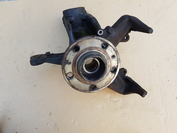
Intervention effectuée sur A2 1.4 TDi 75ch
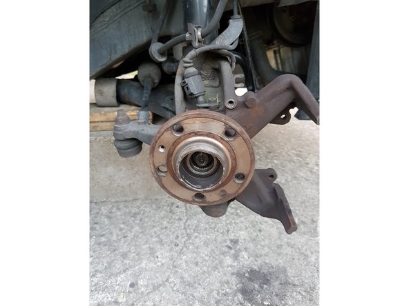
Sur ce modèle il n'est pas possible de changer uniquement le roulement car il fait partie du moyeu, il faut donc changer le moyeu.
N'hésitez pas à pulvériser abondamment tous les filetages des vis et écrous que vous devrez retirer.
-
-
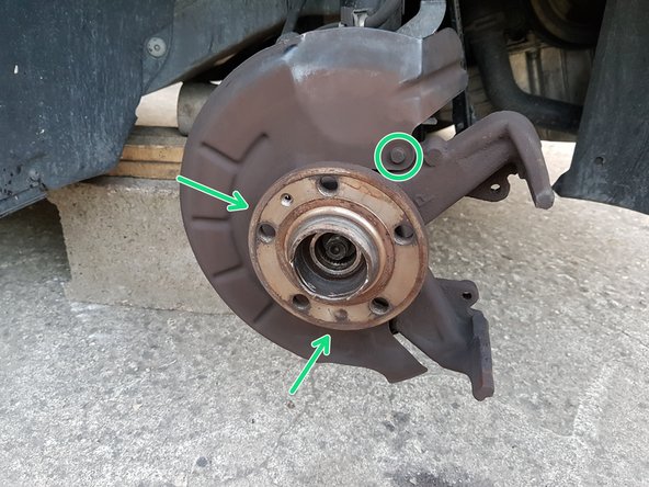
Il faut impérativement une douille de 36mm 12 pans pour dévisser l'écrou.
-
Cet écrou est serré très fort vous aurez donc besoin soit d'une clé à choc soit d'une rallonge.
-
-
-
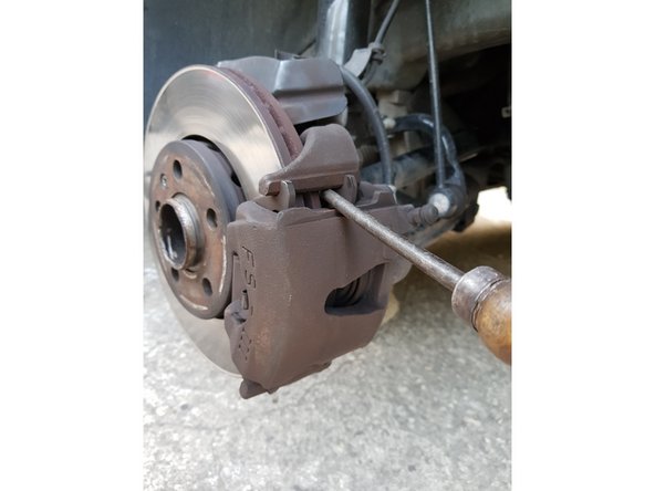
Insérez un gros tournevis plat entre le disque et la plaquette intérieure et faites levier pour repousser le piston vers l'intérieur.
-
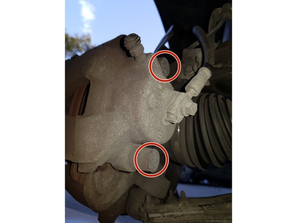
Avec un petit tournevis plat retirez les capuchons des vis d'étrier.
-
Avec une clé BTR de 7mm retirez les 2 vis puis attachez avec de la corde, du fil de fer, des sangles l'étrier au ressort de suspension.
-
L'étrier ne doit absolument pas reposer sur son flexible.
-
-
-
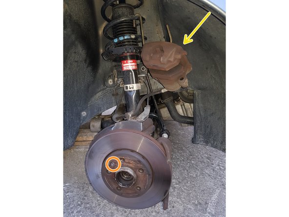
Etrier
-
Retirez la vis du disque de frein avec un gros tournevis puis retirez le disque.
-
Avec une douille de 10mm retirez les 3 vis du carter en métal.
-
-
-
Avec un tournevis plat retirez l'agrafe puis le flexible de son logement.
-
Avec une douille BTR de 5mm retirez la vis du capteur puis le capteur.
-
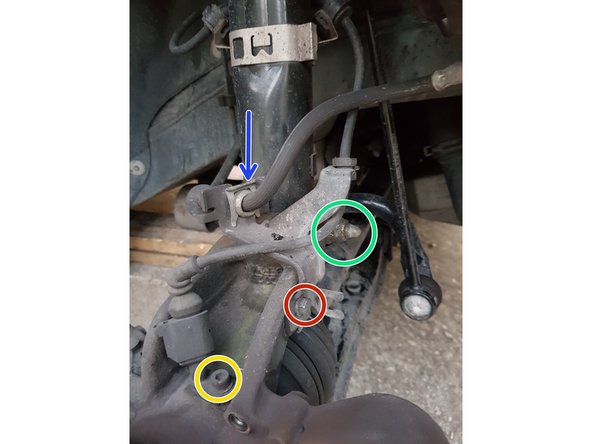
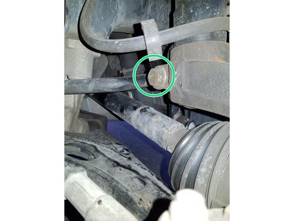
Avec une douille de 10mm retirez la vis.
-
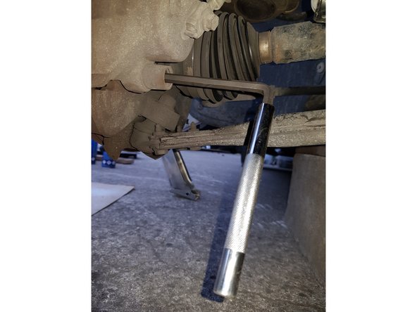
Avec une clé à œil de 18mm bloquez la vis de l'amortisseur et dévissez l'écrou avec une douille de 18mm.
-
-
-
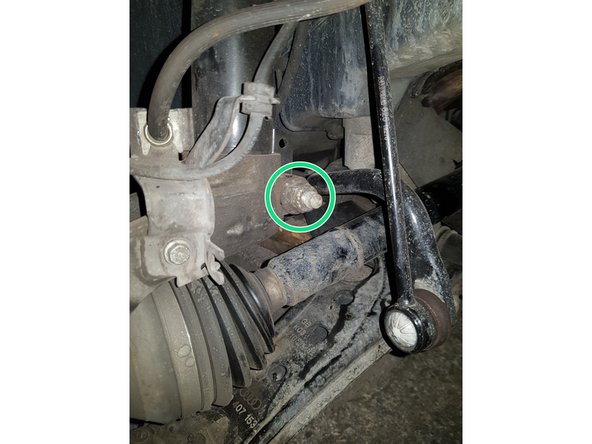
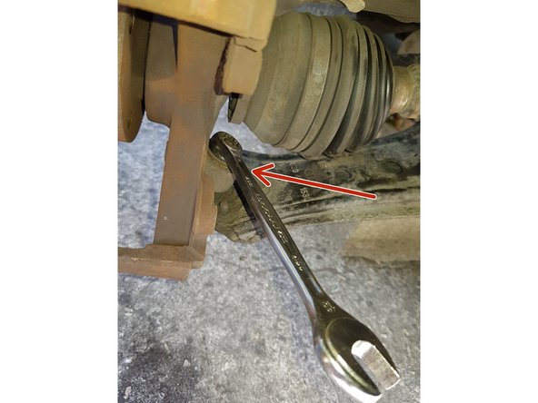
Avec une clé de 18mm retirez l'écrou de la rotule suspension.
-
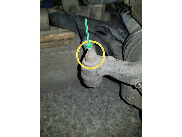
Bloquez la vis de la biellette de direction avec une clé BTR de 6mm.
-
Dévissez l'écrou de la biellette de direction avec une clé de 16mm.
-
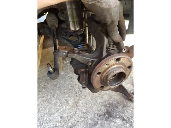
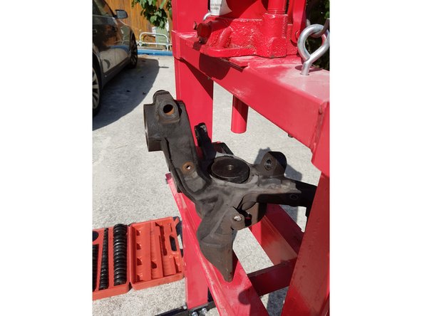
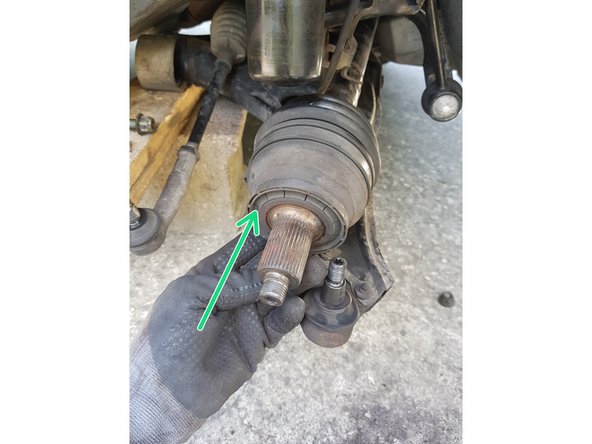
Retirez la fusée en poussant le cardan vers l'intérieur.
-
-
-
L'utilisation d'une presse hydraulique peut s'avérer très dangereuse.
-
Placez une douille d'extraction de roulement de bonne dimension sur le roulement puis sortez-le à l'aide de la presse.
-
-
-
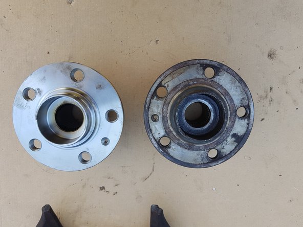
Pour ce kit, SKF a choisi de développer pour la rechange indépendante un roulement de conception différente sans bague d’arrêt. Il n’y a aucune différence dans la procédure de remplacement, des performances identique ou supérieures du roulement. Ce changement de conception a été soigneusement testé et approuvé par les standards qualité SKF.
-
-
-
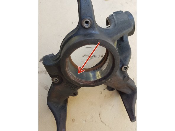
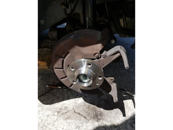
Nettoyez la portée du roulement avec un chiffon ou du papier absorbant.
-
N'utilisez ni abrasif ni brosse métallique.
-
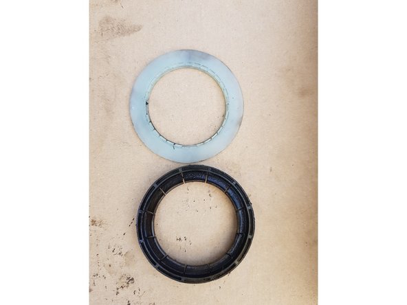
Retirez l'ancien joint en plastique et nettoyez sa portée sur le cardan.
-


Annulation : je n'ai pas terminé ce tutoriel.
Une autre personne a terminé cette réparation.