Introduction
"Votre 206 a un problème de parallélisme ? En plus d'une géométrie, les rotules de direction ont peut être pris du jeu, et il sera impossible de régler quoi que ce soit (posez la question lors du contrôle technique!). Il faudra peut être changer les rotules, avec les barres d'accouplement. Le tout est communément appelé "biellettes de direction".
Le véhicule utilisé est une Peugeot 206 1.4 HDi 70ch
-
-
Tout d'abord, vérifiez les pièces que vous avez. Ici, le kit que j'ai acheté (un pour la roue droite, l'autre pour la roue gauche), comporte plusieurs éléments qui peuvent être achetez séparément. Effectivement, ce tuto propose le remplacement des rotules de direction ET des biellettes. Mais vous pouvez vous contenter des rotules de direction.
-
Ici nous avons donc pour un kit : une rotule de direction, une biellette (avec la rotule interne qui y est fixée), un soufflet pour la biellette, deux colliers métalliques pour maintenir le soufflet, un paquet de graisse pour l'intérieur du soufflet.
-
Après ces menues vérifications, je vous conseille d'enlever le cache protecteur, qui vous libèrera un espace pour plus tard, notamment au moment de manipuler le soufflet.
-
Autre chose qui arrivera par la suite mais que je vous présente maintenant : si vous ne disposez pas de pince à collier métallique (pour serrer les colliers présents dans le kit), des colliers plastiques feront l'affaire, à condition d'avoir une pince à collier ! (3ème photo)
-
-
-
Desserrez les roues avant, puis mettez le véhicule sur chandelles.
-
Enlevez les roues, et vous pouvez maintenant repérer les biellettes de direction.
-
N'étant pas protégées, elles sont certainement dans un sale état ! Un petit coup de brosse métallique vous permettra d'avoir un support propre avant d'attaquer le démontage.
-
-
-
La rotule doit être bien coincée, donc avant de forcer dessus, un petit coup de dégrippant va vous faciliter la tâche.
-
Vous pouvez aussi arroser l'autre bout de la rotule de direction, qui est vissée dans la biellette (juste à côté du contre-écrou).
-
Ensuite, une clé de 16 (ou une douille de 16) vous sera utile pour dévisser l'écrou supérieur de la rotule de direction.
-
Je vous conseille de dévisser COMPLETEMENT l'écrou, avant de déboiter la rotule, car si vous le faites à moitié, la vis tournera ensuite AVEC l'écrou, ce qui vous posera bien des soucis pour finir de dévisser l'écrou.
-
-
-
Après avoir dévissé l'écrou de la rotule de direction (qui est toujours présent sur la photo !), vous pouvez dévisser un peu le contre-écrou. Un petit peu, car cela va vous permettre de déboiter la rotule de direction (donc dévissez de 1 cm par exemple).
-
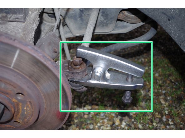
Une fois le contre-écrou desserré, utilisez un arrache rotule pour pouvoir dégager la rotule.
-
Il faut visser, visser, jusqu'à ce que ... crac! l'écartement de l'arrache rotule vous permette de dégager la rotule de la roue.
-
-
-
L'arrache rotule vous a permis de dégager en force la rotule de direction de la roue. Vous pouvez donc la dégager complètement, en faisant jouer un peu l'orientation de la roue.
-
Vous pouvez choisir de vous arrêter la pour changer uniquement la rotule de direction, en la dévissant de la biellette. Mais, ici, on va démonter l'ensemble : Rotule de direction - Biellette - Rotule intérieure.
-
-
-
On va maintenant retirer le soufflet qui protège la rotule intérieure et sa liaison avec la crémaillère.
-
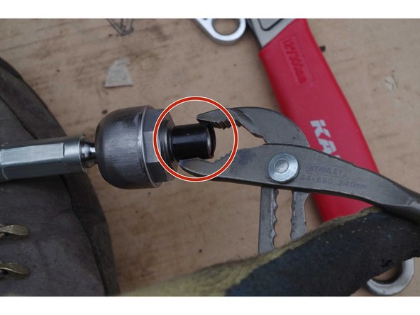
On voit sur la 2ème photo, un circlips qui maintient le soufflet sur le moyeu. Il faut le dégager avec un tournevis plat (en faisant rentrer la tête dans la petite encoche entourée en rouge).
-
Une fois le circlips desserré, on peut tirer sur le soufflet, il vient tout seul.
-
-
-
Si vous ne disposez pas de "démonte biellette", ou de "pince à griffe", un conseil : renoncez ! (et allez acheter illico le matériel !).
-
En effet, il faut dévisser la rotule interne, qui fait la liaison entre la biellette et la crémaillère. La rotule étant ronde (principe d'une rotule!), elle n'a pas de "prise". Ce qui fait qu'une simple clé à molette est inefficace (ça glisse!). D'autant plus que la rotule doit être un peu serrée sur l'arbre.
-
Donc munis (ici) d'une clé à griffe, vous pincez très fort ce que vous pouvez attraper de la rotule, et desserrez de toute vos forces !
-
La principale difficulté ici est l'accès à la rotule. Vous avez très peu de place et n'êtes forcément pas à votre main. Donc je vous conseille très fort un démonte biellette. Cela dit, je l'ai fait sans !
-
-
-
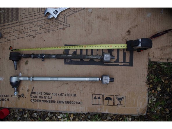
Il faut ensuite, pour ne pas trop dérégler votre géométrie (que vous devrez dans tous les cas faire faire au garage ensuite), mesurez la longueur de l'ensemble : rotule de direction vissée sur la biellette. Réglez la longueur en vissant plus ou moins la rotule de direction dans la biellette.
-
Je vous conseille de mettre le contre écrou à la longueur trouvée. Ainsi, quand vous enlèverez la rotule de direction pour passer le soufflet, vous aurez encore une trace de la longueur à laquelle la rotule doit être vissée. Sinon, vous pouvez aussi compter le nombre de tours que vous vissez dans la biellette.
-
-
-
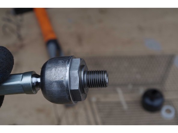
Sur la pièce neuve, un petit cache en plastique protège le filetage qui va être vissée sur la crémaillère.
-
Opération inverse, on vis très fort avec la pince à griffe.
-
Idéalement, un extracteur tulipe permet d'extraire ou de serrer ce genre de rotule, et de pouvoir la serrer au couple constructeur. Ici, j'ai juste serré très fort !
-
Pas de frein filet sur le filetage, si un éventuel démontage ultérieur est nécessaire ...
-
-
-
Mon kit de remplacement est assez complet, car en plus d'un nouveau soufflet (en caoutchouc et non pas en plastique svp !), il fournit aussi la graisse que vous devez mettre à l'intérieur du soufflet.
-
Répartissez donc la bien sur toute la longueur du soufflet, surtout du côté le plus large, ou il y aura la rotule intérieure.
-
-
-
Insérez le soufflet autour de la biellette (vous avez dû retirer la nouvelle rotule de direction que vous avez vissé auparavant lors de la comparaison des pièces).
-
Attention ! Le soufflet est rempli de graisse ! Si vous ne protégez pas le bout de la biellette neuve (avec un sachet plastique par ex), vous allez mettre de la graisse partout ! (et surtout dans le taraudage où viendra se fixer la nouvelle rotule de direction).
-
2 circlips sont fournis dans le kit, mais pour pouvoir les fixer correctement, il faut disposer d'une pince à collier spéciale (que je n'ai pas). J'ai par contre des colliers électriques -type Colson- (et avec une pince!) et cela m'a donc permis de serrer correctement, bien que cela reste une opération délicate !
-
En effet, pour le collier qui maintient le soufflet côté interne, l'accès est TRES réduit. Donc je vous laisse imaginer la difficulté à le mettre en position (bien autour du soufflet, lui même autour de la crémaillère), et ensuite de passer la pince pour serrer le collier.
-
Opération au combien périlleuse, mais une fois que c'est fait, ça ne bougera plus !
-
Sur la 3ème photo, on peut voir le contenu du kit. Il y a Deux colliers métalliques (circlips), le plus grand va d'un côté du soufflet (pour le maintenir à la crémaillère), l'autre plus petit de l'autre côté, pour maintenir le soufflet à la biellette.
-
-
-
Visser la rotule de direction sur la biellette jusqu'au contre-écrou.
-
Mettre la vis de la rotule dans la roue (jouer sur l'orientation de la roue pour faire coincider la vis et le taraudage).
-
Visser le boulon de la rotule (16mm), puis serrez le contre écrou.
-
Vous pouvez alors procéder de même de l'autre côté!
-
Une fois ces étapes terminées, vous pourrez remettre les roues et les serrer !
-
-
-
Vous avez maintenant fini votre remplacement de biellettes, il vous faut, pour le réglage final, passer dans un centre qui vous règlera précisément la géométrie du véhicule.
-
Le garagiste règlera comme vous la position de la rotule de direction dans la biellette (vissée plus ou moins) et verrouillera le réglage avec le contre-écrou, mais avec une précision que vous ne pouvez pas avoir avec les moyens du bord !
-
Cette opération est assez périlleuse, mais simple en soi ! En effet, toute la difficulté est dans l'accès aux biellettes. Assurez-vous également de disposer du matériel adéquat, sans quoi vous perdrez beaucoup de temps, et ne finirez peut être pas l'opération !
Cette opération est assez périlleuse, mais simple en soi ! En effet, toute la difficulté est dans l'accès aux biellettes. Assurez-vous également de disposer du matériel adéquat, sans quoi vous perdrez beaucoup de temps, et ne finirez peut être pas l'opération !
Annulation : je n'ai pas terminé ce tutoriel.
14 autres ont terminé cette réparation.
8 commentaires
merci 0 vous
clair et précis, merci beaucoup pour ce tuto c’est toop !
ne faut-il un outil pour bloquer la crémaillère ?
Non, il suffit de bien braquer à fond, et ça ne bouge pas… En tout cas ça marche comme ça, après peut être qu’il y a plus professionnel comme manière de faire !
Très bon tutoriel.
Pour le collier interne, vous pouvez mettre un serflex très bien serré. C’est beaucoup plus facile à installer et tout aussi efficace.
Merci


