


Introduction
Motorisation du véhicule 1.4 HDi 70 cv
-
-
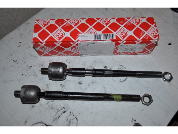
La rotule de direction intérieure se situe entre la crémaillère de direction et la rotule le de direction extérieure
-
Lever et caler l'avant du véhicule. Déposer les roues
-
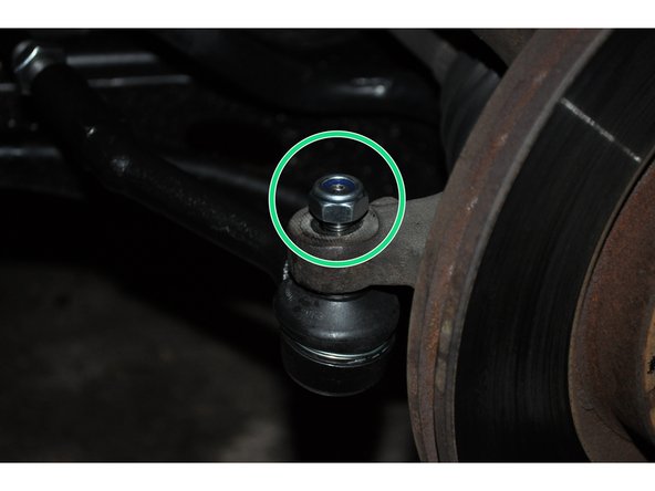
Dévisser l'écrou de la rotule extérieure fixé moyeu de roue
-
-
-
Laisser l'écrou sur le bout du filetage de la rotule puis taper dessus avec un marteau pour la déloger si nécessaire
-
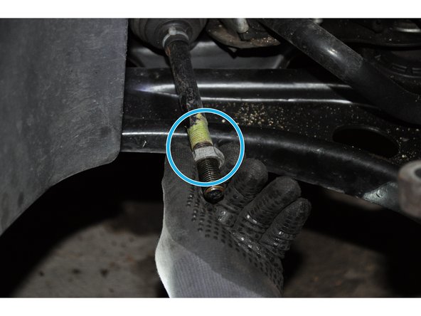
Desserrer le contre écrou de la rotule intérieure en maintenant la rotule extérieure
-
-
-
Déposer la rotule extérieure en comptant le nombre de tours, cela servira de repère pour le remontage
-
Déposer l'écrou en ayant au préalable repéré sa position avec un ruban adhésive
-
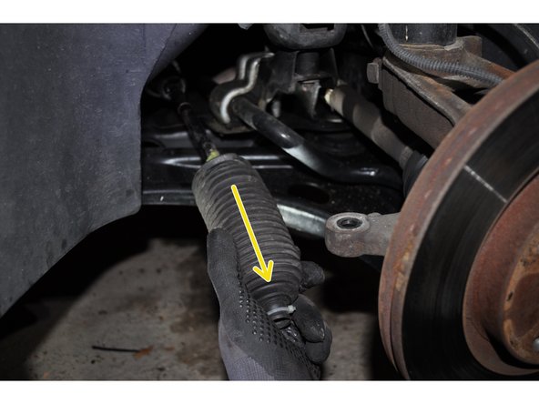
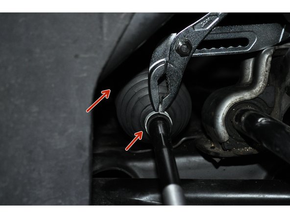
Déposer le soufflet de direction en tirant dessus, il est maintenu de chaque cotés par des colliers en plastique ou métallique
-
-
-
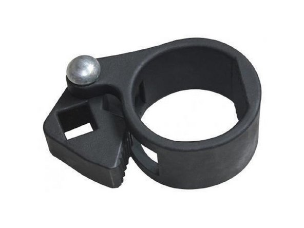
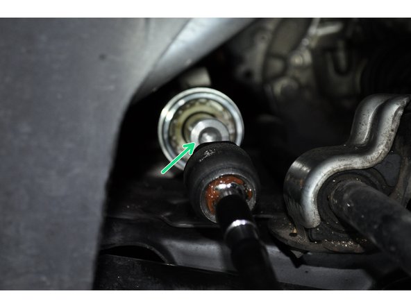
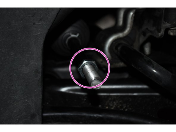
La rotule intérieure est vissée dans la crémaillère de direction
-
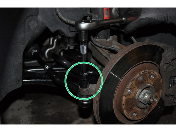
Utiliser une clé démonte biellette, disponible sur Oscaro.com. Cette clé permet la pose et la dépose des rotules axiales de direction sans avoir à retirer la crémaillère
-
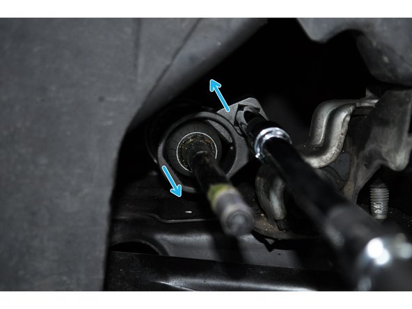
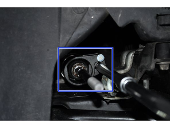
Déposer la rotule avec la clé montée sur des rallonges et un cliquet 1/2
-
-
-
Mettre en place et visser la rotule à la main
-
Placer la clé démonte biellette
-
-
-
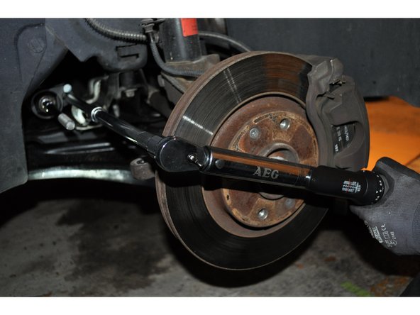
Serrer avec une clé dynamométrique
-
Mettre en place le soufflet et les deux colliers de chaque coté
-
Visser l'écrou en utilisant comme point de repère la mesure sur l’ancienne rotule déposée
-
-
-
Visser la rotule exteriure en compatant le meme nombre de tours qu'à la dépose
-
Placer et serrer l'écrou
-
Faire régler la géométrie chez un spécialiste
-


Annulation : je n'ai pas terminé ce tutoriel.
2 autres ont terminé cette réparation.
